The JUK universal Screw Terminal Block series has the typical features which are decisive for practical applications:
l The universal foot allows the terminal blocks to be easily snapped onto the NS35 or NS32 DIN Rail with G shape.
l Closed screw guide holes ensure screwdriver operation perfect.
l For terminal block with different wire cross-sectional areas, complete accessories are available, such as end plates, partition plates, etc.
l Potential distribution achieved by fixed bridges in the terminal center or insertion bridges in the clamping space.
l Same shape and pitch Grounding Terminal Blocks as the JUK universal series.
l Adopt ZB marker strip system,achieve unified identification.
Din Rail Fuse Terminal Block,Screw Fuse Terminal Block,Din Rail Fuse Holder Terminals,Din Rail Fuse Terminal Wonke Electric CO.,Ltd. , https://www.wkdq-electric.com
Main electrical model and parameters
**What Are the Commonly Used Main Electrical Appliances?**
Main electrical appliances are essential components in control systems, used to switch on and off circuits and send commands to control processes. These devices include buttons, travel switches, universal transfer switches, and master controllers. Additionally, there are other types such as foot switches, proximity switches, reverse switches, emergency switches, toggle switches, and more.
This article primarily focuses on button switches and travel switches, explaining their types, functions, and parameters. Let’s take a closer look at these important components.
**Main Electrical Models and Parameters**
**1. Push Button Switches**
A push button switch is an electrical device that controls small current circuits for short periods. It does not directly control the main circuit but sends manual commands to contactors or relays, which then manage the main circuit. Because of this, it is often referred to as a "master electrical appliance."
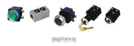
**Button Switch Appearance**
**Button Switch Structure**
The structure of a push button switch typically includes a button cap, a return spring, fixed contacts, movable contacts, a casing, and a linkage mechanism. The contacts can be either normally open (NO) or normally closed (NC).
- **Normally Open Contact:** In its original state, the contacts are separated.
- **Normally Closed Contact:** In its original state, the contacts are connected.
When pressed, a normally open button closes the circuit, while a normally closed button opens it. When released, the spring resets the button to its original position.
In control circuits, normally open buttons are commonly used to start motors, while normally closed buttons are used to stop them.
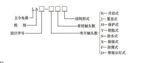
**Button Switch Model Meaning**
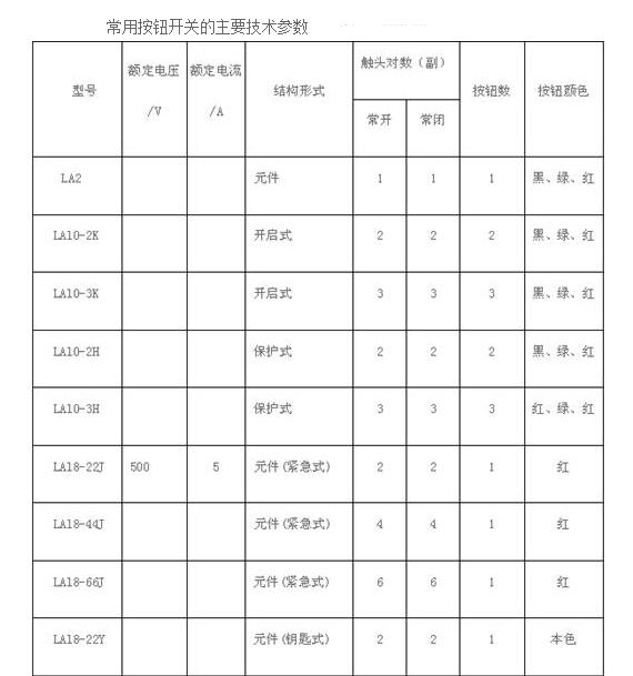
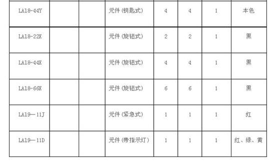
**Main Technical Parameters of Push Button Switches**
**Installation and Usage of Button Switches**
1. When installing buttons on a panel, arrange them neatly and logically, following the order of motor starting.
2. Ensure secure installation and reliable wiring. Red buttons are usually for stopping, while green or black are for starting.
3. Keep contacts clean to prevent short circuits caused by oil or dirt.
4. The button panel and box should be made of metal and properly grounded.
5. In high-temperature environments, use insulating plastic tubes around the wiring screws to prevent short circuits.
6. For button switches with indicator lights, reduce the lamp voltage to avoid overheating and damage.
7. The “Stop†button must be red, the “Emergency Stop†must have a red mushroom head, and the “Start†button should have a protective ring to prevent accidental activation.
**Common Push Button Switch Models**
Popular models include LA2, LA4, LA10, LA18, LA19, LA20, LA25, LA32, LA38, LAY1, LAY3, LAY4, LAY6, and LAY37 (PBC).
**2. Travel Switches**
Also known as limit switches, travel switches are used to detect the position of moving parts in machines. They can be mounted on stationary objects or moving parts. When the moving part approaches the switch, the mechanical linkage causes the contacts to open or close, controlling the circuit accordingly.
**How a Travel Switch Works**
In industrial applications, travel switches are installed at specific positions. When a moving component hits the switch, it triggers the contact to change state, allowing the system to respond appropriately.
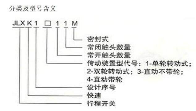
**Travel Switch Classification and Model Meaning**
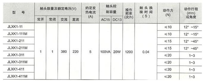
**Main Technical Parameters of Travel Switches**
**How to Choose a Travel Switch**
Consider factors like application, control object, protection level, rated voltage, current, contact type, and quantity. Direct-acting switches may not be suitable for slow-moving parts, as they can cause arcing. In such cases, roller-type or micro-motion switches are preferred.
**Commonly Used Travel Switches**
Examples include LX3, LX8, LX10, LX19, LX21, LX23, LX25, LX29, LX33, LXK3, and LXP1 (3SE3).
By understanding these main electrical appliances, engineers and technicians can better design, install, and maintain control systems in various industrial settings.