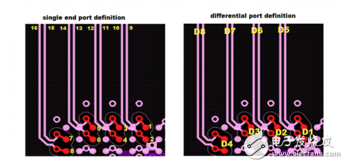
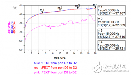
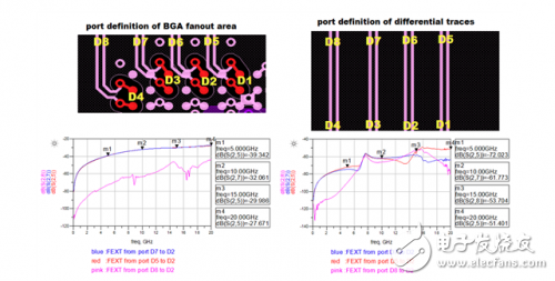
Figure 1: High-speed differential vias for crosstalk (H > 100mil, S = 31.5mil) Figure 2: Crosstalk simulation port definition Figure 3: Crosstalk simulation results between differential pairs Figure 4: BGA fan-out area and differential trace crosstalk simulation results
SWT Gas Generator assembly by gas engine, alternator, radiator, controller, base frame;
. World Famous diesel engine brand: Cummins, Perkins, MTU, MWM, GE, SWT
. World famous AC alternator brand: Stamford, Leroy Somer, Mecc Alte, Marathon, Faraday, SWT
. World famous genset controller brand: Deepsea, ComAp, Deif, SmartGen, Motortech
. Gas Control System: Ignition system, Gas Throttle System, Ga Mixer System, Gas Train Valve System
. Start Battery system
. Optional for Remote Cooling system with CHP & CCHP Control
. CHP- Combine with Heat and Power Electrical system
.CCHP- Combine with Cold, Heat and Power electrical system
Gas Generator,CHP Power Plant,Biogas Generator, Gas Power Station, Natural Gas Generator Guangdong Superwatt Power Equipment Co., Ltd , https://www.swtgenset.com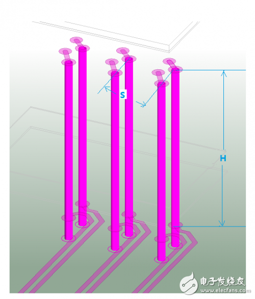
Crosstalk simulation analysis between high speed differential vias
In hardware system design, the primary concern regarding crosstalk typically involves signals passing through connectors, chip packages, and closely spaced parallel traces. However, in certain high-speed designs, significant crosstalk can also occur between differential vias. This paper presents a case study involving simulation and analysis of crosstalk specifically between high-speed differential vias, offering insights into how to address this issue effectively.
**Crosstalk Between High-Speed Differential Vias**
For thicker PCBs, such as those with a thickness of 2.4mm or 3mm, the length of a through-hole in the Z-direction can be quite long—up to nearly 118 mils in the case of a 3mm board. When paired with a BGA component that has a 0.8mm pitch, the fan-out via spacing may only be around 31.5 mils. This close proximity increases the likelihood of crosstalk, especially when multiple differential vias are placed in close proximity.
As shown in Figure 1, the parallel length (H) of two adjacent differential via pairs along the Z-axis is greater than 100 mils, while the horizontal spacing (S) between these vias is only 31.5 mils. In such configurations, where the Z-direction spacing is significantly larger than the horizontal spacing, crosstalk between high-speed differential vias becomes a critical concern. It's important to note that in high-speed PCB design, minimizing via stub length is essential to reduce signal degradation. As illustrated, the stub length on the bottom layer is shorter, or alternatively, back-drilling techniques can be employed to further reduce this impact.