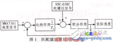
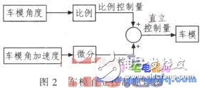
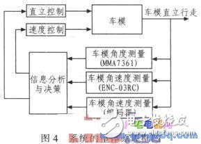
The MC9S12XS128, a cost-effective 16-bit microcontroller from Freescale Semiconductor, serves as the central processing unit in this project. A two-wheeled toy car is used as the control object to demonstrate the principles of balance and motion control. To measure the tilt angle of the model, the ENC-03RC gyroscope and the MMA7361 accelerometer are employed together. These sensors provide data that is processed using a matching filter algorithm to improve accuracy and reduce noise. Based on this information, the vertical movement of the toy car is linearly decomposed, and an upright speed controller is designed to maintain stability. This system enables the two-wheeled vehicle to remain upright and move smoothly. With the rapid economic development in urban and rural areas of China since the beginning of the 21st century, more people have been able to afford private vehicles, which has led to increasing traffic congestion. In response to this challenge, researchers have turned their attention to alternative transportation solutions. Two-wheeled vehicles, compared to tricycles or four-wheelers, offer advantages such as compact size, ease of maneuverability, and convenient storage. These features have made them a popular research topic in recent years, with promising applications in various fields. This paper focuses on a toy car model as a research subject, utilizing modern SMT technology and advanced control theories to explore the dynamics of two-wheeled vehicles. The MC9S12XS128 is a reliable and affordable 16-bit microcontroller, while the ENC-03RC gyroscope and MMA7361 accelerometer are low-cost yet effective sensors for measuring angular velocity and tilt angle. By integrating these components and applying an advanced PID control algorithm, the system can effectively manage the upright operation of the toy car model. This approach ensures accurate and stable control, making it suitable for real-time applications. 1.1 Measurement of the Inclination Angle of the Model To achieve stable upright control of the two-wheeled toy car, it is essential to counteract the gravitational force acting on the model. This requires precise measurement of both the tilt angle and angular velocity. When the car tilts backward, the motor is controlled to rotate in the opposite direction to restore balance. Similarly, when the car tilts forward, the motor adjusts accordingly to maintain stability. The MMA7361 sensor alone can measure the tilt angle, but due to its inherent noise, it is not sufficient for real-time control. Therefore, the system combines the MMA7361 with the ENC-03RC gyroscope and applies a matched filtering algorithm to enhance the accuracy of both angle and angular velocity measurements. This algorithm is illustrated in Figure 1. 1.2 Upright Control of the Car Model As shown in Figure 1, the inclination angle is smoothed through the matched filtering algorithm, while the angular acceleration is obtained from the gyroscope. The upright control is implemented using negative feedback of the angle, allowing the model to maintain a balanced position. Proportional control alone may be insufficient for handling disturbances, so differential control is also introduced to respond to changes in angular acceleration. This combination of proportional and differential control ensures quick stabilization at the equilibrium point. The schematic of the upright control system is presented in Figure 2. 1.3 Speed Control of the Car Model To address issues such as temperature drift in the gyroscope and sensor misalignment, a speed control mechanism is added to stabilize the balance point. Controlling the upright position based on the model’s angle involves a positive feedback process rather than a traditional negative feedback approach. This is because the direction of gravity is opposite to the force that restores the model to its equilibrium state. When the car tilts rapidly, positive feedback is applied to increase motor torque and adjust the tilt angle, rather than reducing the motor output. Since the actuator is a DC motor, the speed and orientation are controlled by regulating the motor's voltage and current. The relationship between torque and current in a DC motor is approximately given by: T = CeφIa (1) where Ce is the motor constant, φ is the flux constant, and Ia is the armature current. This equation shows that the motor behaves as a linear system, allowing the upright and speed controllers to be designed independently. The speed control uses a modified PI controller, as shown in Figure 3. The overall system block diagram, including all control loops, is presented in Figure 4.
Car cable harness, also known as a wire harness, cable assembly, wiring assembly or wiring loom, is an assembly of electrical cables or wires which transmit signals or electrical power. The cables are bound together by connector, terminal, cable ties, sleeves, electrical tape, conduit, PVC tube, corrugate tube, string, or a combination thereof.
Commonly used in automobiles, as well as construction machinery, cable harnesses provide several advantages over loose wires and cables. For example, many aircraft, automobiles and spacecraft contain many masses of wires which would stretch over several kilometres if fully extended. By binding the many wires and cables into a cable harness, the wires and cables can be better secured against the adverse effects of vibrations, abrasions, and moisture.
Car Wire Harness,Wiring Harness,Car Electrical Wiring Harness,American Autowire Mustang Harness Dongguan YAC Electric Co,. LTD. , https://www.yacentercn.com