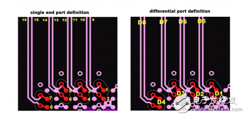
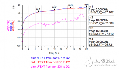
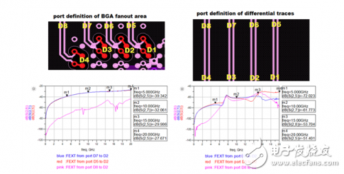
Figure 1: High-speed differential vias for crosstalk (H > 100mil, S = 31.5mil) Figure 2: Crosstalk simulation port definition Figure 3: Crosstalk simulation results between differential pairs Figure 4: BGA fan-out area and differential trace crosstalk simulation results
LED or Metal Halide Lamp Lighting Tower Feature:
The SWT lighting tower is an economical lighting device which easy operate, compact, high performance, and affordable. This series of light tower use a number of advanced and innovative technologies:
1. The control panel is simple with the common configuration: timer, emergency stop button, general alarm light, start switch, light pole control switch and lighting control switch. The power output adopts standard quick insertion output mode, and operation is simple and convenient;
2. Four large-capacity batteries, the lighting system can be powered without the generator set if power sufficiently.
3. The Diesel Generator set is equipped with Kubota or Perkisn Series engine with high quality control system.
4. More humanized maintenance design, all maintenance points are unimpeded ;
5. LED or Metal Halide Lamp lighting system, energy conservation, environmental protection;
6. High-standard mold forming process for all tanks;
7. Internal wiring harness adopts fast plug-in connection mode;
8. Light tower adopts mobile trailer design. Short distance transportation can be directly operated by using tractor-assisted, convenient, fast and efficient;
9. Using anti-rust material, and with high-temperature baking paint process surface, effectively reduce noise up to 15db or more;
10. Using hydraulic power to drive lamp post , and making the unit easy to operate.
11. Four supporting legs install light tower, which can make the installation and dismantling process easily.
Light Tower Genset,Light Tower Genset,Light Power Generator,Lighting Tower Generator Guangdong Superwatt Power Equipment Co., Ltd , https://www.swtgenset.com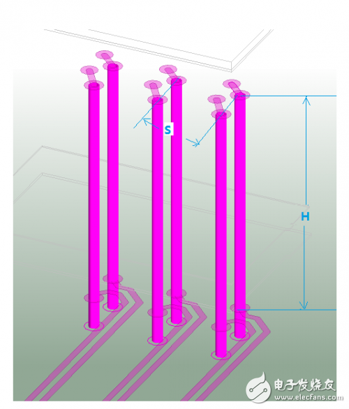
Crosstalk simulation analysis between high speed differential vias
In hardware system design, the primary concern regarding crosstalk typically revolves around signals passing through connectors, chip packages, and parallel traces that are closely spaced. However, in high-speed PCB designs, especially those involving complex BGA (Ball Grid Array) layouts, significant crosstalk can also occur between high-speed differential vias. This paper presents a practical simulation analysis along with solutions aimed at mitigating crosstalk between these critical components.
**Crosstalk Between High-Speed Differential Vias**
For thicker PCBs, such as those with a thickness of 2.4mm or 3mm, the length of a via extending through the board in the Z-direction can be quite substantial. For example, on a 3mm thick board, the via length can reach nearly 118 mils. When paired with a BGA component having a pitch of 0.8mm, the fan-out via spacing is often limited to approximately 31.5 mils, which significantly increases the potential for crosstalk.
As illustrated in Figure 1, when two pairs of adjacent differential vias have a parallel length (H) exceeding 100 mils in the Z-direction, and their horizontal spacing (S) is only 31.5 mils, the risk of crosstalk becomes more pronounced. In high-speed PCB design, it's crucial to minimize the length of via stubs to reduce signal degradation. As shown in the figure, the stub length on the bottom layer is shorter, or alternatively, back-drilling techniques can be employed to further reduce this effect.