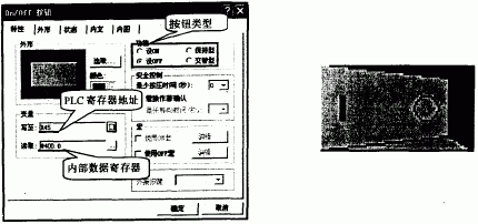
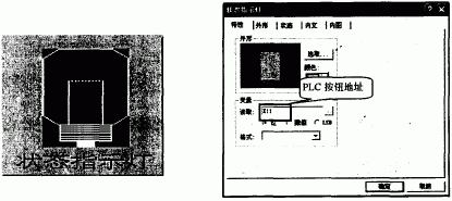
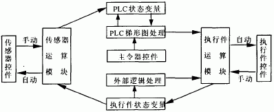
PLC has the advantages of simple structure, good versatility, convenient programming, good flexibility and high reliability. It has become the standard equipment for industrial control and is applied in industrial automatic control III. However, the development, design, verification, and debugging of PLC control systems also need to rely on physical models for simulation tests. This method is inefficient, costly, and unsafe. At the same time, the PLC control system also needs a lot of input and output points to support, which is also the general physical model or simulation software can not be achieved. If you want to achieve the purpose of simulation, you can use the man-machine interface often used in industrial control. Its feature is that you can design as many kinds of input and output devices as you like to simulate static, motion; you can draw what you want. The scene; and it also provides registers, subroutines, timers, counters, etc. for the user to use. Therefore, developers can use the human-machine interface to easily and quickly establish a simulation model for the PLC control system to verify and debug the developed program. 1, PLC simulation implementation PLC is the core of the PLC control system, so the realization of PLC simulation is the key to achieve the entire system simulation. The essence of realizing PLC simulation is to make a certain device able to imitate all input and output devices except the PLC in the PLC control system, and these devices can operate according to user programs (such as ladder diagram programs). In order to achieve the above requirements, the human-machine interface was selected as an analog device. It has a wealth of input and output indicators, designed to simulate a variety of equipment on site, and instantly display the operating status of the equipment; its simulated master control device can be operated directly on the touch screen; it also has a large internal Registers and powerful application of macro instructions, so that the human-machine interface can perform numerical calculations, logic judgments, flow control, numerical transmission, numerical conversion, timers, counters, etc. via internal macro instruction functions, and can also simulate more intelligent The requirements of the control equipment; In addition, its operating mode is similar to the PLC, using a cyclic scan; more importantly, the register data between the PLC and the human-machine interface can be directly read, as shown in the variable column of Figure 1. This solves the problem of input and identification of the user program well and realizes the simulation of the PLC. 2. Simulation of external devices External equipment can be divided into three categories: one is the main commander, such as buttons, switches, etc.; one is the implementation of various indicators, cylinders, motors, electromagnets, etc.; there is a class of sensors, such as various trips Switches, proximity switches, etc. 2.1 Simulator implementation of the master There are many types of masters, such as alternate, hold, reset, and numeric input buttons. The man-machine interface is more convenient to implement. Simply use the editing software of the man-machine interface to draw the button, as shown in Figure 2, and then confirm what type of button is in the button properties, as shown in the function bar of Figure 1. In the simulation, simply press the screen directly to operate the button. Figure 1 Component Property Diagram Figure 2 Button Diagram 2.2 Implementation of the executor Executables are also diverse in real systems. To facilitate simulation, they are divided into open and close parts and reciprocating parts. Opening and closing parts refers to the short stroke, fast speed, and the implementation of the other, such as the light and the light does not shine, the motor is running and not running; and the relative length of the stroke, slow, in the journey of ~ 9 n - I stayed in the implementation of the merger of reciprocating parts, such as cylinders, screws and so on. The following uses the opening and closing indicator light as an example to illustrate how to implement the actuator simulation. In the simulation interface, draw a light as shown in Figure 3, in Figure 4 indicator properties will read the variable to PLC address, directly controlled by the PLC. 2.3 Sensor Simulation Implementation Corresponding to the actuators, the sensors are also divided into two types, opening and closing sensors and reciprocating sensors. The opening and closing sensor is used to determine the opening and closing state of the opening and closing member; the reciprocating sensor is used to detect whether the reciprocating member is in a certain position. Here, an opening and closing sensor is taken as an example to illustrate the method of sensor simulation. Figure 3 LED diagram Figure 4 LED property block diagram Shown in Figure 5 is a ball screw drive control system driven by a stepper motor. Both ends of the screw are photoelectric position switches, requiring the motion platform to be either manually or automatically controlled. In the automatic control mode, after the start-up, the operating platform will first run to A. When it reaches A, it will automatically return to B, and so on. In the manual control mode, the parking at the destination can be started in A place or B place, and it must be started again manually before it can continue running and the emergency parking control pin can be realized. Analog X6, X7 photoelectric switch can use man-machine interface editing software, the preparation of a subroutine shown in Figure 6, according to the implementation of the code in the execution state variables to read the state of the tested actuator (data). When reaching the predetermined position (predetermined value), the result is output to the PLC's input terminal and the sensor's indicator light. Figure 5 One-dimensional position control diagram Figure 6 Subroutine 3, the processing of the relationship between external devices For a device in a PLC control system, its movement depends not only on the PLC instructions, but also on the relationship between it and other devices. For example, the PLC command drives a cylinder, the cylinder pushes the object A, and the A pushes the object B. Then, to make the object B move, not only the relative movement of the cylinder directly controlled by the PLC is required, but also the object A is required to be in the proper position. This is the so-called external logic relationship. These relationships may consist of external electrical, pneumatic and hydraulic circuits, and mechanical structures, which can sometimes be complicated. However, the man-machine interface editing software has rich macro instructions internally and can simulate various external logic relationships. Users can also compile several subroutines according to their own requirements to reflect their complex logic relationships, so that they can accurately substitute between external devices. The logical relationship to achieve simulation results. 4, the overall framework of the simulation system Figure 7 is the overall framework of the entire simulation system, and its working process is: Figure 7 The overall block diagram of the simulation system (1) The sensor operation module reads the actuator state variables, and after processing, stores the test results in the PLC state variables that represent the virtual PLC input terminals; FIG. 8 is a flowchart of a human-machine interface program compiled based on the overall block diagram of the simulation system. The overall structure of the simulation program uses a scanning method of operation, which is in line with the working characteristics of a real PLC. Figure 8 block diagram of the process of running 5, application examples Using the PLC control system simulation platform introduced in this paper, a simulation model for one-dimensional position control is established as shown in Fig. 5. The input and output points of the PLC are used for l4, and the total length of the program is 196 sentences. Two subroutines were written for the simulation model established on the man-machine interface of the system. Although the system is not too complicated, but all aspects are already complete (such as the main controller, actuators and sensors, etc.), can reflect the basic rules of the simulation of the general control system. In addition, the man-machine interface editing software can also be used to perform multiple off-line and online simulations of the simulation model, which can verify the correctness and reliability of the system design. Road Traffic Signs are graphical symbols that display traffic regulations and road information. They can make traffic regulations visually, concisely and concisely expressed. At the same time, they also express the content that is difficult to describe in words. They are used to manage traffic and indicate the direction of driving to ensure the smooth flow of roads and the safety of driving. Applicable to highways, urban roads and all special highways, with the nature of the law, vehicles, pedestrians must comply with. Road Traffic Signs Road Traffic Signs,Traffic Light Sign,Road Safety Signs,Highway Road Traffic Signs Yangzhou Heli Photoelectric Co., Ltd. , https://www.heli-eee.com


(2) The user's ladder diagram program is processed according to the state variables of the PLC and the status of the master controller, and the final result is output to the execution module.
(3) The executor operation module drives the actuator action according to the input instruction, and refreshes the actuator state variable according to the status of the executor;
(4) Some actuators are processed by external logic relations according to the status of other actuators, and then the actuator computing module drives the actuators. There are manual input functions for actuators and sensor arithmetic modules, which are prepared for human-made faults. 
Research on Simulation of PLC Control System Based on Human Machine Interface
0 Preface