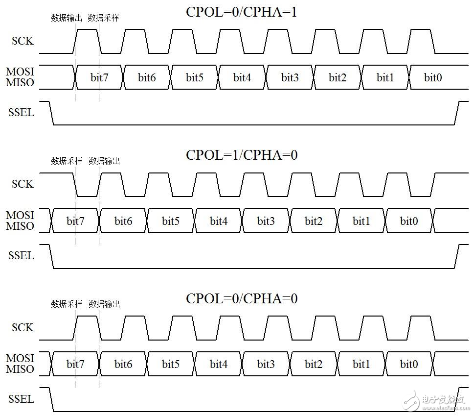
SPI is the abbreviation of English Serial Peripheral Interface, which is the serial peripheral interface as its name suggests. SPI is a high-speed, full-duplex, synchronous communication bus. The standard SPI also uses only 4 pins. It is commonly used for communication between microcontrollers and EEPROM, FLASH, real-time clock, digital signal processor and other devices. The SPI communication principle is simpler than I2C. It is mainly master-slave communication. This mode usually has only one host and one or more slaves. The standard SPI is 4 lines, which are SSEL (chip selection, also written as SCS). SCLK (clock, also written as SCK), MOSI (Master Output/Slave Input) and MISO (Master Input/Slave Output). SSEL: Select the enable signal from the device chip. If the slave is low enabled, when the pin is pulled low, the slave is selected and the master communicates with the selected slave. SCLK: The clock signal, generated by the host, is somewhat similar to the SCL for I2C communication. MOSI: The channel through which the host sends instructions or data to the slave. MISO: The channel through which the host reads the status or data of the slave. In some cases, we can also communicate with a 3-wire SPI or a 2-wire SPI. For example, when the host only sends commands to the slave, the slave does not need to reply to the data, then the MISO can not. When the host only reads the data of the slave, and does not need to send instructions to the slave, the MOSI can not When a slave is a slave, the slave's chip select can sometimes be fixed to the active level and always enabled. Then SSEL can be omitted. If the host only sends data to the slave, then Neither SSEL nor MISO can be used; if the host only reads data from the slave, neither SSEL nor MOSI can be used. 3 and 2 lines of SPI Everyone needs to know what is going on, and the actual use is also applicable, but when we refer to SPI, it generally refers to the standard SPI, which refers to the form of 4 lines. The host of SPI communication is also our single-chip microcomputer. There are four modes in the process of reading and writing data timing. To understand these four modes, we must first learn the following two terms. CPOL: Clock Polarity is the polarity of the clock. What is the concept of the polarity of the clock? The whole process of communication is divided into idle time and communication time. If SCLK is high level before and after data transmission, then CPOL=1, if the idle state SCLK is low level, then CPOL=0. CPHA: Clock Phase is the phase of the clock. When the master and the slave exchange data, there is a question of when the host outputs data to the MOSI and when the slave samples the data, or when the slave outputs the data to the MISO and when the host samples the time. This data. A feature of synchronous communication is that all data changes and samples are accompanied by a clock edge, which means that the data always changes or is sampled near the edge of the clock. A clock cycle must contain a rising edge and a falling edge, which is determined by the definition of the cycle, but the two edges are not specified. And because the data takes a certain amount of time from the moment it is generated to its stability, if the host outputs data to the MOSI on the rising edge, the slave can only sample the data on the falling edge. Conversely, if one party outputs data on the falling edge, then the other party must sample this data on the rising edge. CPHA=1, it means that the output of the data is on the first edge of one clock cycle. Whether this edge is a rising edge or a falling edge depends on the value of CPOL. CPOL=1 is the falling edge, otherwise it is Rising edge. Then the sampling of the data is naturally on the second edge. CPHA=0, which means that the sampling of data is on the first edge of a clock cycle, and it is also determined by CPOL. Then the output of the data is naturally on the second edge. Think about it, there is a problem here: when a frame of data begins to transmit the first bit, the data is sampled on the first clock edge, then when is it output? There are two cases: one is the edge enabled by SSEL, and the other is the last clock edge of the previous frame of data. Sometimes both cases will take effect at the same time. Let's take CPOL=1/CPHA=1 as an example, and let the timing picture come out for everyone to see, as shown in Figure 15-1. Figure 15-1 Timing diagram of SPI communication (1) As you can see in Figure 15-1, when the data is not sent and after the transmission is completed, SCK is high, so CPOL=1. It can be seen that at the first edge of SCK, MOSI and MISO will change, and at the same time the second edge of SCK, the data is stable. At this moment, the sampled data is suitable, that is, the rising edge is one clock cycle. The trailing edge latches the read data, ie CPHA=1. Note the last most concealed SSEL chip select. This pin is usually used to determine which slave is communicating with the host. The remaining three modes, we put the picture out, simplifying the combination of MOSI and MISO, we take a closer look at the study, clear all the theoretical processes, and help you to understand the SPI communication, such as Figure 15-2 shows. Figure 15-2 Timing diagram of SPI communication (2) In terms of timing, is SPI much simpler than I2C? Without start, stop, and acknowledge, the UART and SPI are only responsible for communication when communicating, regardless of whether the communication is successful, but I2C has to respond to the message to get information about the success of the communication, so the UART and SPI are relatively Timing is simpler than I2C. Unmanaged POE Industrial Switches
PoE power supply switch refers to a switch that can provide network power supply for remote powered terminals through a network cable. It includes two functions: network switch and PoE power supply. It is a relatively common power supply device in PoE power supply systems.
PoE power supply switch refers to a switch that can provide network power supply to remote powered terminals through a network cable. It includes two functions: network switch and PoE power supply. It is a relatively common power supply device in PoE power supply systems. The port supports an output power of 15.4W, which conforms to According to the IEEE802.3af standard, the port supports an output power of 30W and conforms to the IEEE802.3at standard. It supplies power to standard POE terminal equipment through network cable power supply, eliminating the need for additional power wiring. A POE switch conforming to the IEEE802.3aT standard, the port output power can reach 15-60W. In layman's terms, a POE power supply switch is a switch that supports network cable power supply, which can not only realize the data transmission function of ordinary switches but also supply power to network terminals at the same time .
Network Switch 5 Port,Poe Switch 5 Port,Gigabit Switch 5 Port,Unmanaged Poe Industrial Switches Shenzhen Scodeno Technology Co.,Ltd , https://www.scodenonet.com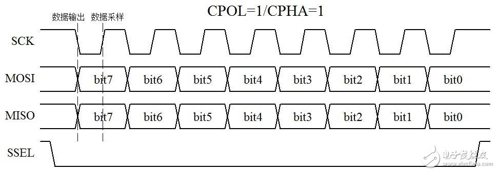
POE (Power Over Ethernet) means that without any changes to the existing Ethernet Cat.5 cabling infrastructure, it is used for some IP-based terminals (such as IP phones, wireless LAN access points AP, network Cameras, etc.) can provide DC power supply technology for such devices while transmitting data signals. The POE technology can ensure the normal operation of the existing network while ensuring the safety of the existing structured cabling, minimizing costs. POE is also known as a power supply system based on local area network (POL, Power over LAN) or Active Ethernet (Active Ethernet), sometimes also referred to as Power over Ethernet for short. This is the use of existing standard Ethernet transmission cables to transmit data and data at the same time. The latest standard specification of electric power, and maintains compatibility with existing Ethernet systems and users. The IEEE 802.3af standard is a new standard based on the POE of the Ethernet power supply system. It adds related standards for direct power supply through the network cable on the basis of IEEE 802.3. It is an extension of the existing Ethernet standard and the first international standard for power distribution. standard