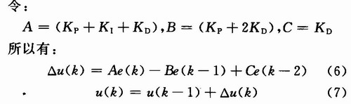
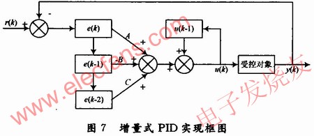
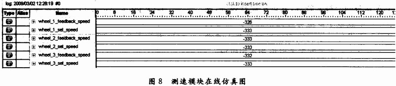
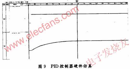
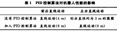
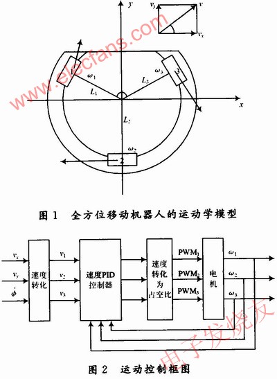
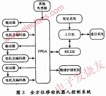
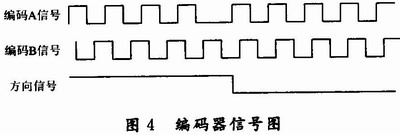
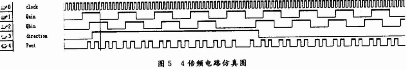
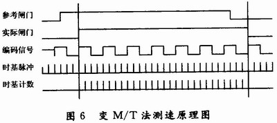
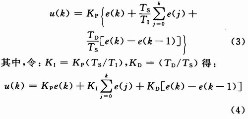
0 Preface At present, due to its excellent flexibility, the omnidirectional mobile robot has become the most ideal choice for RoboCup medium-sized soccer robot competition. The robot motion control has always been the main factor that directly affects the performance of the robot, and is also one of the hot spots in the research of mobile robots. This paper studies a method of using FPGA technology to realize a three-wheel omnidirectional mobile robot motion control system. Compared with dual DSP structure, DSP + CPLD structure, and DSP + special integrated circuit structure, this method is simple, reliable, and highly scalable Features. And the FPGA design is simple, easy to use, and the development cycle is short, which can realize the real SOPC system. 1 Omnidirectional mobile robot motion model Suppose the speed of the robot in the world coordinate system is ε = [vx, vy, φ], then when vx = O, vy ≠0, φ = O, the robot makes a linear movement in the front-back direction, when vx ≠0, vy = 0 When φ = 0, the robot makes a linear motion in the left-right direction. When vx = 0, vy = 0, and φ ≠0, the robot makes a rotation motion. In Figure 1, ω1, ω2, ω3 are the rotation angular velocity of the three driving wheels, R is the omnidirectional wheel radius; L1, L2, L3 is the horizontal distance from the center of the robot car body to the center of the three groups of omnidirectional wheels, with L1 = L2 = L3 = L. α is the angle between the first two rounds, and the other two angles are both 180 ° -α / 2. Then the relationship between the speed in the robot coordinate system and the three-wheel speed is as follows: It can be seen from equation (1): after knowing the speed requirements of the robot in the plane world coordinate system, the speed requirements of the driving wheel can be obtained, and then the corresponding control signal is issued to the motor. 2 Motion control scheme The overall design idea of ​​this system is shown in Figure 2. First, the RS 232 interface is used to realize the communication between the PC and the underlying control chip FPGA. After receiving the speed under the relevant robot coordinate system, the FPGA coordinates the robot The speed value is converted into the angular velocity of the three omnidirectional wheels of the robot, and the corresponding angular ratio is calculated to generate the corresponding duty cycle, and the PWM waveform corresponding to the duty cycle is generated. The output signal is connected to the DC servo motor driver and then collected by FPGA Calculate the actual angular velocity value of the wheel with the quadrature-encoded disc signal, and do PID speed closed-loop control. In view of the advantages of FPGA module replication, PID closed-loop control is performed for each omnidirectional wheel separately. 3 System hardware design The block diagram of the three-wheel omnidirectional mobile robot system used is shown in Figure 3. The host computer mainly completes the collection, processing, path planning of image information, and realizes communication with the off-site referee box. The lower computer is mainly FPGA, which mainly realizes the collection of three rounds of encoded signals, PID speed closed-loop control, kicking control, motor control signal generation, and other sensor information collection, etc., and is responsible for information interaction with the upper computer . This design just completed the motion control part of the lower computer. 3.1 Orthogonal coding signal acquisition and speed measurement The output signal of the incremental photoelectric encoder is shown in Figure 4. The two-phase signals of A and B are orthogonal square wave pulse trains with a phase difference of 90 °. Each pulse represents a certain angle of rotation of the measured object, and the phase relationship between A and B reflects the direction of rotation of the measured object. Design 4 frequency multiplication and direction discrimination circuits in FPGA. This design uses 2 outputs: one output direction and the other output pulse, and simulates the direction multiplication circuit, as shown in Figure 5. There are three methods for measuring the rotation speed based on the pulse count: M method, T method, and M / T method. The M method is suitable for high-speed measurement occasions, and has a large error at low speed; while the T method, on the contrary, has accurate measurement at low speed and a large error at high speed. This design uses the method described in the literature. This method is shown in Fig. 6, and the reference gate time is set to a fixed value, which is only used as a reference signal and an encoded signal to determine the actual gate time. The gate time determined in this way is twice the full cycle of the measured signal, which can effectively improve the measurement accuracy. The measured speed is: 4. The principle of incremental PID control and its FPGA implementation The mathematical model of the actual robot inevitably has a certain degree of parameter uncertainty, and the orthogonal omnidirectional wheels of the three-wheel omnidirectional mobile robot will alternately contact the ground while walking and produce some uncertain friction torque, which will give The precise control of the robot brings difficulty. In order to accurately control the three-wheel omnidirectional mobile robot, the system uses PID speed closed-loop control algorithm to adjust the speed of the robot's three omnidirectional wheels. Let the sampling period be TS and discretize the continuous PID formula to get the digital PID algorithm expression: Where: k is the sampling number; u (k) is the computer output value at the kth sampling time; e (k) is the computer input error value at the kth sampling time; e (k-1) is the k-1th The input error value at each sampling time; Kp is the proportional coefficient; KI is the integral coefficient; KD is the differential coefficient. Although this algorithm is more intuitive, because it is a full output, each output is related to all the past states. During the calculation, e (k) needs to be accumulated, and the amount of computer calculation is large. So the incremental PID algorithm was produced: The above formula (7) is an incremental PID control algorithm. Only the control increment is output, and the erroneous action has little influence, and the control increment is only related to the sampling values ​​of the last few times, and it is easy to obtain a better control effect through weighting processing. According to the above formula derivation, combined with the working characteristics of FPGA, this paper designs an incremental PID implementation structure suitable for FPGA. It can be seen from Figure 7 that the incremental PID control algorithm program structure, as long as the last three error sample values ​​can be weighted. This can be realized in parallel within the FPGA. The structure of the shift part is similar to the implementation structure of the FIR filter. The difficulty is that the FPGA design is proficient in signed numbers and ensures that the accumulator cannot overflow. An efficient hardware test method and system test method. It can obtain and display real-time signals of programmable system on chip (SOPC). It can be downloaded into FPGA together with design files to capture FPGA internal nodes and I / O leads. The state of the foot, just like using a real logic analyzer, performs online simulation of the design, but does not affect the work of the hardware system. In order to check whether the measured actual speed value of the omnidirectional wheel is accurate, an online simulation of the designed speed measuring module is carried out. Set each omni-directional wheel to rotate at a fixed speed, and compare the measured actual speed value with the set speed value, as shown in Figure 8. In the embedded logic analyzer, the PID module was also tested online. Experimental conditions: under no-load conditions, the speed of the motor is frequently changed, and the speed value and set value after PID adjustment in the FPGA are observed through the embedded logic analyzer. Figure 9 shows the speed set value of the omnidirectional wheel With feedback speed value. The three-wheel omnidirectional mobile robot is different from the two-wheel differential and has great flexibility. Moreover, due to the different loads of the three omnidirectional wheels, the robot cannot get out of a straight line. To achieve precise control of the robot, a prerequisite is that it can walk out of a very straight line. In order to check the control performance of the robot, the following experiment is designed: the robot walks at a fixed speed in four directions of forward, backward, left and right, first observe the situation when PID control algorithm is not added, and then observe the situation when PID control algorithm is added. The results of the experiment are shown in Table 1. Analysis: Because the three omnidirectional wheels of the robot bear different loads, that is, the PWM of the same duty cycle, the actual speed of the three wheels is not the same, which makes it impossible to accurately synthesize the three-wheel speed of the robot. Speed, which in turn affects the robot's control trajectory. According to Figure 1, the load of wheel 1 and wheel 3 of the robot is equivalent, and the load of wheel 2 is relatively large. When the PID controller is not added, although the front and rear movements are approximately linear within a certain range, the speed of the robot cannot reach At the expected speed, the left and right motion trajectory is a circle, and the set left and right movement speed of the robot also determines whether the robot rotates in a clockwise or counterclockwise direction. After the PID control algorithm is added, the speed of the wheels is corrected, and the robot can move back and forth and left and right at the expected set speed, especially the left and right movements are approximately straight lines within a certain range, and are no longer circles. It can be seen that the PID closed-loop control algorithm significantly improves the control performance of the robot. 5 Conclusion Aiming at the current common scheme of using DSP as the core to realize the underlying motion control system of football robots, a method for realizing the underlying motion control system of three-round omnidirectional mobile football robots using FPGA is proposed. Through the application practice on the three-wheel soccer robot, it is found that this FPGA-implemented solution has good real-time performance and high accuracy, and because of the many pins of the FPGA itself, its scalability is strong, such as Configure other sensors such as digital compass and other peripheral information sensors through the serial port. At the same time, this design has important reference value and practical value for studying the implementation scheme of the multi-motor robot motion control system. In addition, due to the strong followability of the omni-directional wheel and easy slipping, the direction is easily affected when precise control is implemented, and the PID closed-loop control algorithm has a longer reaction time, and the parameters require more time for debugging. In the research, we will study more precise control algorithms to achieve precise control of the robot.
Drum
type Rice Cooker
Features
This type rice cooker is famous with drum type appearance, which
is easy operation and easy clean.
There are two type of inner pot , one type called white pot which is without non-stick but cheaper price
.another one called non-stick pot is polished with emery, Also there are two
type non-stick with different price ,it`s depending on different demands to
use.
And the inner pot cannot be burned on the stove, which will make
the pot transfigured and bad contact with the heating plate. While cooking , the
heating plate or the fuse is most likely to be burned for the bad contact of
the inner pot and the heating plate, Besides, make sure to dry the pot before
putting into the outer shell of the rice cooker ,or else the drops of water
flowing on the heating plate, will make the heating plate rusted.
Applications
Many
peoples are used drum type rice cooker for congee and soup, some of peoples are
prefer to use this type rice cooker for steaming.
Drum Rice Cooker,Drum Shape Rice Cooker,Electric Drum Rice Cooker,Multifunctional Drum Rice Cooker Guangzhou Taipeng Electrical Appliances Technology CO., LTD. , https://www.kettles.pl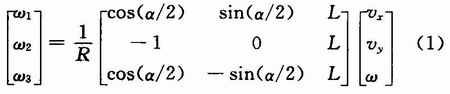
![]()
![]()