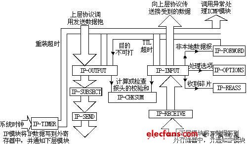
introduction In order to realize network information processing, the embedded system must have a powerful network connection function. The network connection function of the embedded system not only needs to transmit information, but also must have the corresponding information recognition capability to improve the network security of the system. In recent years, driven by the development of embedded systems and SOC (system-on-chip) technology, microprocessors or single-chip systems embedded with IP protocols have emerged [3], laying the foundation for the application of embedded network technologies. But for industrial equipment, especially for the instruments used in industrial production, the use of software embedded IP protocol has the disadvantages of not being able to process in parallel and being too costly. Therefore, using hardware to implement the IP protocol is of great significance. IP hardware circuit design has two methods: embedded processor and ASIC. When designing the IP protocol using the embedded processor method, you need to select the corresponding processor and additional circuits, and compile the corresponding software to implement the IP protocol according to the embedded processor. This method can use the existing IP protocol software, which is more convenient to implement. The use of ASIC technology to design IP protocols is a hardware implementation of IP methods. The implementation of IP protocols is all performed by hardware. This implementation method has the advantage that the execution of the IP protocol is not interfered by software, and has a certain anti-interference ability of the IP protocol layer. The ASIC implements the IP protocol to implement a dedicated digital hardware circuit, which only needs to implement the IP protocol function through the corresponding control signal, and has a relatively high performance-price ratio. In response to the needs of industrial equipment for IP protocol, this paper designs and implements an ASIC device that can complete the function of IP protocol. For industrial control equipment, this device is a dedicated device that implements the IP function. As long as the data to be sent is transmitted to the device, the communication process and the control system can be operated in parallel. Any digital industrial equipment can use this IP protocol device to directly connect to an IP-based network. 1. Protocol analysis and IP circuit structure design The function of the IP protocol is to pack and unpack the data from the upper layer protocol, and transmit it among the IP protocol modules through the datagram until the datagram reaches the destination module [2]. There are IP modules on each host and gateway device in the Internet network, and datagrams are transmitted to the destination address by routing network addresses among modules. The format of the IPv4 datagram header is shown in Figure 1. When IP provides network layer services, it uses a unified header so that the IPs in each subnet can process the data according to the header. Version Number Header Length Service Type Total Length Logo DFMF Right to Life Protocol Header Checksum source address Destination address Options (indefinite) Figure 1 IP protocol header format The following 4 key technologies are used in IP to achieve datagram transmission: (1) Type of service (ToS). ToS is a parameter set that represents the services that the Internet can provide and is used to specify the quality of service that users want. The service type is used by the gateway. It can be used for a specific network or for the next network to pass through. It can also be used for selecting the actual transmission parameters on the next gateway to route the datagram. (2) Time to Live (TTL). Time-to-live is the time that the user sets the datagram during the transmission of the network. The survival time is set by the sender and processed by the route passed. If the survival time is zero before reaching the destination node, the IP will automatically discard the datagram. (3) Options (opTIONs). Options include time stamps, security, and special routing requirements. Options are important for control functions, but are generally not necessary for normal communication. (4) Header checksum (checksum). The purpose of setting the header check code is to ensure the correct transmission of data. If the check fails, IP will discard the entire datagram. It must be noted that, unlike the simple communication protocol used by general industrial control systems, the IP protocol does not immediately notify the sender when it finds a check code error, but discards a piece of message it has just received and leaves the task of correcting the message error Complete for the TCP protocol. This method not only improves communication efficiency, but also simplifies transmission quality and guarantees procedures. In designing IP protocol ASIC hardware circuits, there are several issues to consider: (1) The core processor of the application system implements the use of IP protocol devices through control signals. Therefore, it must be considered how to implement data exchange between the core processor and the IP hardware circuit through the hardware circuit. (2) If the IP hardware is applied to terminal equipment (such as control equipment of an industrial control system) rather than as a switching node, the part of the IP protocol related to routing processing can be omitted. (3) In order to ensure the robustness of the IP protocol, the circuit design must pay great attention to the problem of uneven delay of different circuit parts in the operation of the circuit parallel protocol. The delay of all functional circuits does not exceed the allowable range. If necessary, speed must be sacrificed to ensure the correctness of the protocol operation. (4) If the amount of data transmitted each time is not large (for example, as an industrial network control system composed of industrial equipment), the message fragmentation processing in the IP protocol may not be considered. As long as the application system makes the length of the data sent each time meet the length requirements of an IP datagram, it can correctly use the IP network to transmit data. This not only simplifies the hardware circuit, but also saves the buffer memory capacity. According to the above discussion, the design of the IP dedicated circuit is actually to realize the external handshake and internal pipeline processing circuit through the counter, register, RAM. Because the receiving and sending are independent of each other, the circuit design can divide the receiving and sending into two separate parts. Therefore, the block diagram of the dedicated circuit of the IP protocol ASIC is shown in Figure 2. 2. IP protocol ASIC circuit handshake operation In IP protocol devices, the task of the sending circuit is to add an IP header to the data to be sent, and then send the packed IP datagram to the MAC layer. The task of the receiving circuit is to perform header verification and de-reporting on the received IP report, and finally transmit the data to the microprocessor system. An important issue in designing IP protocol hardware circuits is the mechanism for receiving and sending datagrams. There are two keys to using hardware to implement the IP protocol: one is pipeline operation, and the other is data storage. Pipeline operation refers to the implementation of the IP protocol using a pipeline method, and each operation step is implemented in parallel. As a network layer protocol, the speed of IP protocol operation depends on two factors: one factor is the datagram storage method, and the other factor is the MAC layer's sending and receiving speed. From the position of the IP layer, since the access network of the IP network works in full-duplex mode, the working clock as a hardware device must be based on the sending and receiving clocks. In this design, the application system calls the IP protocol signal as the transmission circuit operation permission signal, and the MAC layer calls the IP protocol signal as the transmission and reception trigger synchronization signal. The technology of synchronous trigger clock parallel control is adopted to realize the pipeline parallelization of the IP protocol operation steps. deal with.
- Multiple USB Charger Extension Socket provide quick
charging for your mobile electronic devices.
- Smart Charging: 5V 2.4A/3.4A/4.2A/4.8A/6A Usb Ports Extension Cord support smart charging. Protect your devices from over charging damage.
- Multiple Outlets Power Strip With Usb Ports allowing you to plug in
various electronics and electrical devices.
- PC/ABS flame retardant housing, phosphor bronze+pure copper high conductivity Power Strip Usb .
-- Qualified Power Cord Receptacle Extension With Usb allowing you
extend the outlet 6 feet (2 meters) away from the wall or even further with long power strip.
Power Strip With Usb Power Strip With Usb,Power Strip With Usb Ports,Usb Ports Extension Cord,Power Strip Usb,Receptacle Extension With Usb,USB Charger Extension Socket ZhongShan JITONGLONG Plastic Hardware Co. Ltd. , https://www.toukoo-electronics.com![]()