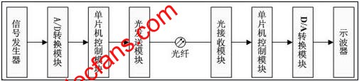
In recent years, the construction of informatization has been developing rapidly, and people's demand for multimedia communications such as data, voice, and images has become increasingly strong, which has greatly accelerated the development of optical fiber communications. Because traditional Ethernet no longer meets the needs in terms of transmission distance and coverage, and optical fiber communication has the advantages of long transmission distance, large information capacity, and good confidentiality, optical fiber communication is of great significance for information construction. 1. The principle of optical fiber communication Optical fiber communication technology stands out from optical communication and has become one of the main pillars of modern communication, playing an important role in the modern telecommunications network. The information source converts user information into original electrical signals, which are called baseband signals. The electrical transmitter converts the baseband signal into a signal suitable for channel transmission. If the conversion requires modulation, the output signal is called a modulated signal, and then the modulated signal is input into the optical transmitter to be converted into an optical signal. The optical carrier passes through the optical fiber line After being transmitted to the receiving end, the optical receiver converts the optical signal into an electrical signal. The function of the electrical receiver is opposite to that of the electrical transmitter. It converts the received electrical signal into a baseband signal. Finally, the information sink recovers user information. 2. The design plan of the system This design uses the optical sending module, optical receiving module and optical fiber to design and make a simple optical fiber transmission system. The overall plan is shown below. A signal generator is used to generate an analog signal to be transmitted, which is converted to a digital level through an A / D conversion circuit, and then data is transmitted through an optical transmission module and an optical reception module, and processed through a D / A conversion and data processing circuit. The processed result can be observed by comparing the output waveforms of the oscilloscope and the signal generator. In order to realize the A / D conversion function, the D / A conversion function and the ability to process signals, a single-chip control module is specially introduced. The picture shows the design plan of the system The A / D conversion module of this design uses ADC0809 analog / digital conversion chip, the single-chip microcomputer uses AT89C51, the optical transmission module uses HFBR-1414T, the optical receiving module uses HFBR-2416T, and the D / A conversion module uses It is DAC0832 digital / analog conversion chip. (1) Sending module Optical transmitters and receivers are important devices in modern optical fiber communication systems. The optical transmitter used in this design is the HFBR-1414T type photoelectric device produced by Agilent. It is an integrated optical transmission module. It has LED light-emitting diodes made of AIGaAs inside. The wavelength of the emitted light is 820 μm and the spectrum width is 30 μm. And, there are a variety of optical fiber interfaces, such as 50 / 125μm, 62.5 / 125μm and 100 / 140μm. HFBR-1414T has high luminous efficiency and can guarantee to work under small drive current. Therefore, the energy consumption is low and the stability is good. (2) Receive module The optical receiver is the HFBR-2416T model, which belongs to a low-cost, high-performance optical connector in the HFBR-0400 series produced by Agilent. It is widely used in the fields of optical fiber analog communication and digital communication. The output of HFBR-2416T is an analog voltage signal, which can be applied to analog optical communication systems and digital optical communication systems. When the optical receiving circuit is working, the optical signal transmitted by the optical fiber is converted into a voltage signal by the HFBR-2416T. The function of the circuit automatic gain control limiting amplifier and logic level comparator is to convert the voltage signal output by the HFBR-2416T into TTL or ECL Digital level. In addition, a current limiting resistor of 10Ω and a bypass capacitor of 0.1uF need to be connected between the Vcc of the DHFBR-2416T and the power supply to remove power supply noise. If necessary, a more complex filter circuit can be added. Usually the optical receiver composed of HFBR-2416T and the optical transmitter composed of HFBR-1414T are used together to form a complete optical communication transceiver system. in conclusion: The design principle of this system is simple, the device is not complicated, and the scalability is very strong, easy to apply. It can realize the expansion of multi-channel common transmission. In order to improve the accuracy of the output signal and further reduce the distortion, a chip with a larger number of bits can be used. The number of bits of ADC0809 used in the design is 8 bits. There are currently 12 and 16 bits. The more digits, the more accurate the converted result, and the smaller the waveform distortion observed by the oscilloscope. The expansion of the design can further improve its transmission quality. As long as the optical receiving module HFBR-2416T is placed on the transmitting end, the receiving end is added with the optical transmitting module HFBR-21414T and corresponding software expansion is performed, and the expansion of the bidirectional communication function can also be realized.
4 Spliters DC Power Supply
Power supply splitter , it is 12v dc power supply, our special design for 4 channel output terminal.
Features:
Wide input range: 100-240V, 50/60Hz.
Full current,all using brand new capacitors
Large transformer,full 5A output
Pure aluminum heat sink,it can effectively prevent the power adapter is overheating
Humanized design A wall-mounted ear hooks
All glass fiber main board,ensure the power long life
Industry the highest standard 4 times aging test.
It can fulfill 4 group CCD camera, output voltage is changeable.
Protection: short circuit, over current, overload, over voltage.
3 years warranty
Product application:
Application to CCD camera, Infrared LED light camera. Infrared dot array lamp camera.
4 Splitters Dc Power Supply,Network Switch Power Supply,Network Controlled Power Supply,Network Backup Power Supply Guangdong Steady Technology Co.LTD , https://www.steadysmps.com