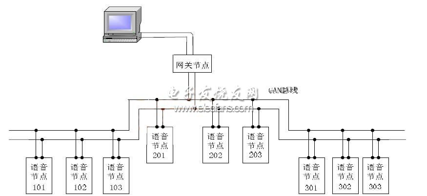
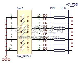
In view of the shortcomings of the existing analog broadcasting system, such as weak anti-interference ability and short transmission distance, the research of the digital voice communication system based on CAN bus is carried out. The overall composition of the voice communication system is given, and the node modules are designed in detail. The core part adopts the built-in CAN controller PIC18F458 single-chip microcomputer as the controller, and the independent CAN transceiver CTM8251 forms a CAN transceiver module; it adopts the AMBE-1000 chip with low transmission rate and high call quality as the voice encoder. Tests show that reliable and high-quality voice real-time communication can be achieved between nodes. introduction The CAN bus is used in many industrial fields such as the automotive industry, coal mine safety monitoring system, and intelligent instrument system due to its short frame, lossless arbitration, multi-master working mode, and strong interference capability. The digital voice communication system based on CAN bus is designed using the characteristics of CAN bus. Using this system, the dispatch room can notify all the staff in the mine to evacuate safely at the same time, and direct rescue and disaster relief in accordance with the mine emergency plan; underground personnel can also contact the dispatch room in time to report the situation; the underground also has local communication functions It is convenient for underground personnel to contact and report things directly. 1 Overall structure of voice communication system The overall structure of the voice communication system based on CAN bus is shown in Figure 1. Figure 1 overall system diagram The system consists of a host computer PC, a gateway node, a voice node, a communication cable, a terminal, etc. It uses a bus network and a multi-master access mechanism. The ground can operate the gateway node through the host computer PC to realize any call (that is, on-demand mode) to each voice node in the underground, call of each group of voice nodes (that is, multicast mode) or all calls (that is, broadcast mode); Each underground voice node can also call the gateway node, and the gateway node uploads the ID of the voice node to the host computer PC; and each underground voice node can communicate with other voice nodes in the same group. In the CAN bus structure, the nodes can be flexibly accessed, which is the most advantageous place of the CAN bus network. At the same time, because there is no master and slave, each node can receive information or send information when the bus is idle This is another important advantage of CAN bus. 2 Voice node hardware circuit design Voice data is input through the microphone, amplified by the MAX9814, and then sent to the digital-to-analog conversion module for A / D conversion, and then compressed and packaged by the voice processing module to the microprocessor. The microprocessor transmits the data to the CAN transceiver. On the bus; the information on the bus is transmitted to the microprocessor through the transceiver, and is transmitted to the voice processing module through the microprocessor, which is decompressed, sent to the analog-to-digital conversion module for D / A conversion, and outputs the analog signal through the power amplifier module The power is amplified and sent to the speaker, and finally the speaker outputs the voice signal. The overall structure of the voice node is shown in Figure 2. Figure 2 Overall structure of voice node 2.1 Processor module The processor module is the computing core of the voice communication node. All device control, task scheduling, energy calculation and function coordination, communication protocols, data integration, and data storage procedures will be completed with the support of this module, so the choice of processor is Voice communication node design is crucial. This design uses a PIC18F458 [4] microcontroller with a CAN control module as a microcontroller (MCU) to achieve operation control of AMBE-1000, CTM8251, MAX9814, MAX9736 and other chips. At the same time, the microcontroller also needs to control some buttons and indicators . In the hardware design of the voice node, the PIC18F458 and each part of the interface circuit and reset circuit are shown in Figure 3. Figure 3 PIC18F458 and various parts interface Part of the circuit of the DIP switch is shown in Figure 4. It is used to set the identifier (ID) of the voice node. ID9-ID0 correspond to 10-1 of the DIP switch in sequence. The 10-6 key on the DIP switch is the group number. The 5-1 key is the node number, and the level value of the DIP switch is ON is "0", otherwise it is "1". Each node judges whether it needs to receive a message based on the identifier. Figure 4 DIP switch Silicon Transistor are solid-state semiconductor devices with functions such as detection, rectification, amplification, switching, voltage regulation, and signal modulation. The transistor acts as a variable current switch and can control the output current based on the input voltage. Unlike ordinary mechanical switches (such as Relay and switch), transistors use electrical signals to control their opening and closing, and the switching speed can be very fast. The switching speed in the lab can reach more than 100GHz. Silicon Transistor Silicon Transistor, Power Transistor, IGBT Transistor, N-Channel Transistor, PNP Transistor YANGZHOU POSITIONING TECH CO., LTD. , https://www.yzpst.com