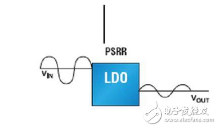
When designing a hardware system, you need to choose the right power supply chip. Whether you are designing a consumer digital electronic or wireless sensor device, you need to weigh the various functional requirements of the product. The power IC selection can only be made after the noise suppression, power consumption, voltage drop, and supply voltage and current are evaluated and prioritized. Each signal path requires a "clean" power supply. Power management is the last part of the system design. Figure 1 shows an example system of how to power a signal path. Design a wireless product that requires ultra-low power consumption. A 3AH battery can work for 5-6 years. This requires the entire communication mechanism to have power-saving functions. It also requires the product itself to have ultra-low power consumption capability. Products that require ultra-low power consumption need to be analyzed from several components of the product: 1) Power section 2) RF part 3) CPU part 4) Other parts Here I combine my work to do an analysis of the power section: Select the power chip principle: 1) Select manufacturers with mature technology, good product quality and good cost performance. 2) Select products with high operating frequency, reduce peripheral components and reduce costs. 3) The package is small, but the output current should be considered. Generally, it is small package small current, large package large current. 4) Choose a manufacturer with good technical support, especially when a small company chooses a power device, and the small company ignores you. 5) Select the complete information, preferably in Chinese, the sample can be applied, it is best to have free, short delivery period, it is best not to stop production The above is to analyze from a large level, including design and procurement. From the level of technical requirements to analyze: LDO device selection The LDO selects four elements: differential pressure, noise, quiescent current, and common mode rejection ratio. From the perspective of power saving, mainly look at quiescent current, some LDO quiescent current is very small, about 1UA, which is the power consumption of LDO when working. This parameter is very important in power saving. The smaller the better, the better, but not May be 0, LDO's power consumption has two indicators: one for quiescent current and one for SET_OFF current, to distinguish! ! There is also a pressure difference, this is a good understanding, a pressure difference of 0 is an ideal LDO. I am using the S-1206 series, Japan, using Japanese goods, no way, SOT23, passing friends introduced a Chinese product to me, the quality is good, and the R1180X series, it seems to be Japanese. All of the above are IQ values ​​below 5 ua. But to do RF LDO, you need to consider: noise suppression, because RF is too sensitive to noise. The power supply ripple ratio (PSRR) is an AC parameter that reflects the input ripple rejection capability under the condition that the output and input frequencies are the same. Unlike noise, noise usually refers to the mean squared value (RMS) of the output voltage noise of an LDO at a certain input voltage in the frequency range of 10 Hz to 100 kHz. The unit of PSRR is dB, and the formula is as follows: PSRR=20 log (△vin/△vout) Power supply affects signal path performance Figure 2. Power Supply Rejection Ratio (PSRR) is a measure of the attenuation from input to output ripple/noise. Not surprisingly, the power supply affects the integrity of the analog signal, which ultimately affects overall system performance. An easy way to improve signal path performance is to choose the right power supply. A key parameter that affects the performance of an analog signal path when selecting a power supply is noise or ripple on the power line. Noise or ripple on the power line can be coupled into the output of the op amp, increasing the jitter of the phase-locked loop (PLL) or voltage-controlled oscillator (VCO), or reducing the SNR of the ADC. Low noise and low ripple power supplies also improve signal path performance. The source of noise or ripple on the power line is versatile. High-speed data and high-frequency signals in the system itself generate noise. If the PCB's printed lines and connecting lines are not properly designed, the effect of the transmitting antenna can be formed. Digital ICs, such as microcontrollers and field-programmable gate arrays (FPGAs) and complex programmable logic devices (CPLDs), have very fast edge-jumping velocities, and the magnitude of the current varies greatly, producing electromagnetic interference into the system. The IC silicon generates thermal noise internally due to random motion and collision of molecules at temperatures above absolute 0 degrees Celsius. There are three common ways to minimize noise and ripple in the signal path: very careful system PCB layout, proper power supply bypass handling, and proper power supply selection. Although the specific design of the PCB depends on the system, in general, the layout of the PCB needs to include the correct device layout, the minimum length of the signal path connection line, and the physical ground. Bypassing the power rail is a common method that is commonly recommended in analog IC product manuals to filter out noise. The signal path IC can have separate analog, digital, and PLL power inputs, and each is recommended to have its own independent bypass processing. PLL power supplies and analog power supplies are the most sensitive to noise and ripple. Bypass capacitors, RC capacitors, and EMI suppression filters minimize power supply noise into the signal path. Proper power selection reduces the effects of noise and ripple on the signal path IC. When choosing a power supply, the designer first makes a basic choice between the switching converter and the linear regulator. Switching converters provide higher frequencies, and higher frequencies mean lower overall system power consumption. Linear regulators provide an easy-to-use solution while reducing noise/ripple on the power rail. Using a linear regulator to reduce noise and ripple improves signal path performance. Undoubtedly, in portable wireless products, that is, LDOs with large PSRR are required for their own work, but LDO products with large PSRR are currently available. However, there are few products that can take into account these two indicators. I found one. The LDO of S1167 has a power consumption of 9 UA and a PSRR of 70 dB. It should be said that the two indicators are taken into account, but it is Japanese goods. Just considering PSRR, and IQ does not matter at around 45, it is good to use AS1361, PSRR can be more than 90dB. DC-DC power supply selection For DC-DC, the conversion efficiency, ripple, input and output voltage, etc. are mainly considered. When selecting a DC/DC converter, the circuit design should pay attention to the output current, high efficiency, miniaturization, and output voltage requirements: 1. If the required output current is small, the FET built-in type can be selected; when the output current needs to be large, the external FET type is selected. 2. The following considerations regarding efficiency: If the ripple voltage at heavy load is prioritized and noise is removed, the PWM control type can be selected; if the efficiency at low load is also required, the PFM/PWM switching control type can be selected. 3. If miniaturization is required, a high-frequency product that can use a small coil can be selected. 4. In terms of output voltage, if the output voltage needs to reach a fixed voltage or higher, or an unfixed output voltage is required, the variable output VDD/VOUT split type product can be selected. DC-DC working mode PFM and PWM comparison: The three control modes of PWM control, PFM control and PWM/PFM switching control mode have their own advantages and disadvantages: DC/DC converter is boosted or stepped down by internal frequency synchronous switch, and controlled by changing the number of switching times. , thereby obtaining the same output voltage as the set voltage. During PFM control, the switch will stop when the output voltage reaches above the set voltage, and the DC/DC converter will not perform any operation until it drops to the set voltage. However, if the output voltage drops below the set voltage, the DC/DC converter will start switching again to bring the output voltage to the set voltage. The PWM control also switches synchronously with the frequency, but it minimizes the current flowing into the coil when the boost setpoint is reached, and adjusts the boost to match the set voltage. Compared with PWM, the output current of PFM is small, but the PFM-controlled DC/DC converter stops when it reaches the set voltage or higher, so the current consumed becomes small. Therefore, the reduction in current consumption can improve the efficiency at low loads. Although the PWM is inferior in efficiency at low load, the noise filter is relatively easy to design and the noise is eliminated because the ripple voltage is small and the switching frequency is fixed. If you need to have the advantages of PFM and PWM at the same time, you can choose PWM/PFM switching control DC/DC converter. This function is controlled by PWM during heavy load, and automatically switches to PFM control at low load, that is, it has the advantages of PWM and the advantages of PFM in one product. In systems with standby mode, products with PFM/PWM switching control can achieve higher efficiency. Advantages of high frequency: By actually testing the efficiency of PWM and PFM/PWM, it can be found that PWM/PFM switched products are more efficient at low loads. As for the high frequency, by increasing the frequency of the DC/DC converter, it is possible to achieve high current, miniaturization, and high efficiency. However, it must be noted that efficiency can only be improved by the characteristic fit of the coil. Because when the DC/DC converter is high-frequency, the switching loss will increase due to the increase in the number of switching times, resulting in a decrease in efficiency. Therefore, efficiency is determined by a compromise between improved coil performance and increased switching losses. By using a highly efficient product, a small coil can be used with respect to a coil with a lower inductance value, and the same efficiency and output current can be obtained even with a small coil. External device selection: In addition to the need to pay attention to the characteristics of the DC / DC converter itself, the choice of external components can not be ignored. The coils, capacitors, and FETs in the external components have a large impact on the characteristics of the switching power supply. The so-called characteristics here refer to the output current, the output ripple voltage, and the efficiency. Coil: If you need to pursue high efficiency, it is best to choose a coil with a small DC resistance and a small inductance value. However, if a coil with a small inductance value is used for a lower frequency DC/DC, the rated current of the coil will be exceeded, and the coil will be magnetically saturated, causing deterioration of efficiency or damage to the coil. Moreover, if the inductance value is too small, the ripple voltage will also increase. Therefore, when selecting a coil, please note that the current flowing to the coil does not exceed the rated current of the coil. When selecting a coil, it is necessary to comprehensively determine the conditions based on the output current, the frequency of the DC/DC, the inductance of the coil, the rated current of the coil, and the ripple voltage. Capacitance: The larger the capacity of the output capacitor, the smaller the ripple voltage. However, a larger capacity also means a larger capacitance volume, so choose the most suitable capacity. Transistor: As an external triode, compared with bipolar transistors, because the switching speed of the FET is faster, the switching loss will be smaller and the efficiency will be higher. Die-Casting Products,Led Housing Die Casting,Aluminum Die Casting Product,Aluminum Die Casting Led Yangzhou Huadong Can Illuminations Mould Manufactory Co., Ltd. , https://www.light-reflectors.com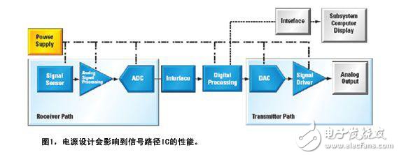
Discussion on the experience and feelings of low power and low noise power circuit design
Design a wireless product that requires ultra-low power consumption. A 3AH battery can work for 5-6 years. It needs the power-saving function of the whole communication mechanism, and the ultra-low power consumption capability of the product itself. Then, when designing a low-power, low-noise power supply, how to plan, select, and debug a step-by-step design to design a power supply circuit with low power consumption and low noise. Which of these should be noted? ? Please see the engineer's design experience and skills to share!