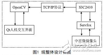
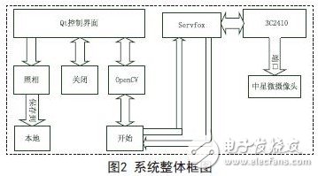
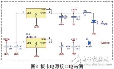
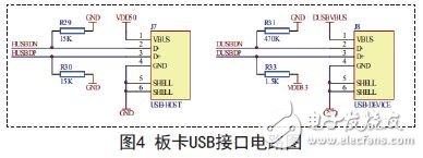
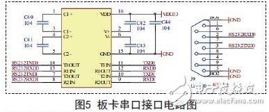
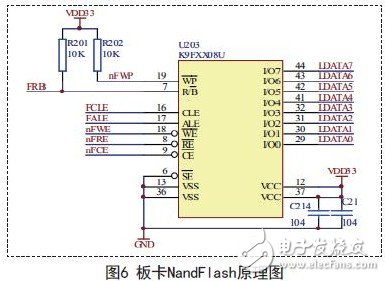
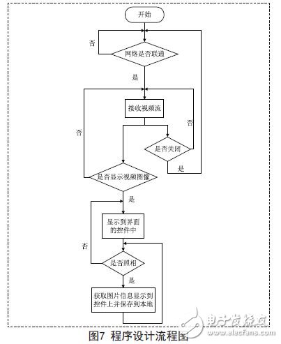
1. Overall design of the plan 1.1 Design main module The remote video surveillance system is a software system and a hardware system. The software system includes a human-computer interaction interface developed by the software Qt on the Windows system, a third-party OpenCV library, the hardware system includes the S3C2410 board, and the servfox collection tool (used Linux system compilation), Zhongxing micro camera. The overall module design block diagram is shown in Figure 1: The Qt human-computer interaction interface belongs to the software part of the system, mainly through the interface designed by Qt to process the video images transmitted from the terminal. OpenCV is also part of the software in this system. It mainly allows Qt to import OpenCV library files. It is implemented in Qt through some interfaces provided by OpenCV, so that the video images transmitted from the terminal can be smoothly displayed. The TCP/IP protocol is currently the most popular and commonly used network transmission protocol. In this system, the software part and the hardware part of the system are connected through the TCP/IP protocol, and the video information collected by the terminal is transmitted to the client through the network cable. On the computer, as long as the network address of both ends is pinged, the transmission can be realized. The S3C2410 board is in the hardware part of the system, and is also the core of the hardware part. The camera is connected to the camera through the USB port of the S3C2410 board, and the video information collected by the camera is received, and the collected video information is transmitted through the network line. Servfox belongs to the hardware part of the system. It is mainly transplanted to the S3C2410 platform. After detecting the camera, the servfox is started to complete the task of collecting video information through instructions, and the specific video information is processed by the S3C2410 in the hardware part. In the hardware part of the satellite micro camera is connected to the USB port of the S3C2410 to complete the video picture capture. 1.2 System design overall structure As shown in Figure 2, the overall structure is divided into two parts: the terminal and the client. The client is mainly the human-computer interaction interface of Qt. By calling the display of the third-party library, the specific camera, close, and start operation. The completion of the human-computer interface is completed. The main thing in the terminal is the S3C2410 board. The Zhongxing micro camera is connected around the board to collect the video of the terminal. The servfox tool transplanted to the board operating system is used to complete the transmission of the video stream. The connection between the terminal and the client is mainly connected through a network cable, the terminal sends video information, and the client processes the video information at the same time, so that it becomes a whole. 2. System hardware design 2.1 power interface circuit The circuit diagram of the power interface of the board is shown in Figure 3: The power supply voltage of the board is DC5V, and the 5V voltage is 3.3V and 1.8V working voltage through the LDO chip AS1117-3.3V and AS1117-1.8V respectively, 1.8V is used for the board core. In addition, the 1.8V voltage is supplied to the RTC internal RTC through a Schottky diode. The RTC power VCCRTC is also connected to the expansion socket. If necessary, the battery can be connected externally. 2.2 USB interface circuit The circuit diagram of the USB interface of the board is shown in Figure 4: The board has a USB main port and a USB slave port. The circuit is mainly a pull-up resistor. The USB slave port can detect cable insertion actions and can cause an INT10 interrupt. In this design, the USB main port of the board is mainly used to connect the camera. 2.3 RS232 serial port circuit The circuit diagram of the serial port interface of the board is shown in Figure 5: The UART0 and UART1 of the S3C2410 should be used for TTL-RS232 level conversion with the MAX3232 chip. The RS232 serial port corresponding to UART0 is led out by DB9 socket for easy debugging. UART1 corresponds to the RS232 serial port from the expansion socket. There is also UART2 (TTL level) on the expansion socket. In this design, the DB9 socket is mainly used to connect to the computer, which is convenient for debugging the board. 2.4 NandFlash chip of the board The schematic diagram of the board's NandFlash chip is shown in Figure 6. The K9F1208 is Samsung's NandFlash chip, and the S3C2410 board has a Nand controller inside, so the K9F1208 is directly connected to the S3C2410 and can be booted from NandFlash. 2.5 Zhongxing Micro Camera The ZC301 model camera produced by Zhongxing Micro is selected in the terminal. The reason why this camera is selected is because the S3C2410 originally supports this model. It does not need to be reconfigured. It only needs to load the camera driver in the S3C2410. The driver can be found in the Centos system. The zc0301.ko in this directory is the driver. Copy it to the S3C2410 and execute the insmod zc0301.ko. 3. System software design The overall design of the system is fully described above, but all the design of the system requires the design of the program to support, Figure 7 shows the flow chart of the program design. 4. Conclusion The program design part of the design scheme of the remote monitoring system based on S3C2410 and Qt introduced in this paper is strictly in accordance with the flow of the above figure. The video transmission can be continued in the case of network connection. The rest of the operation is mainly concentrated on people. On the machine interaction interface. The remote monitoring system designed in the scheme can not only display the video status of the terminal in real time, but also capture the image at any time and store the acquired image in real time, and the image is clear and easy to monitor. And it can be applied to a variety of occasions: factory warehouse management, mobile phones, PDAs and other small or handheld embedded devices. Air Fryer Oven,Power Air Fryer Oven,Power Airfryer Oven,Power Oven Air Fryer Ningbo Anbo United Electric Appliance Co.,ltd , https://www.airfryerfactory.com