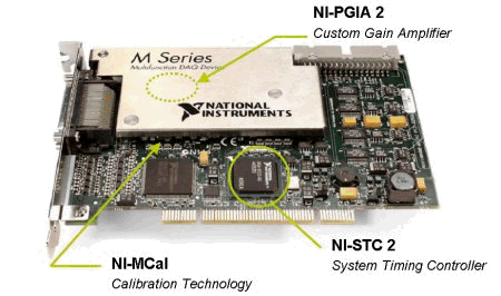
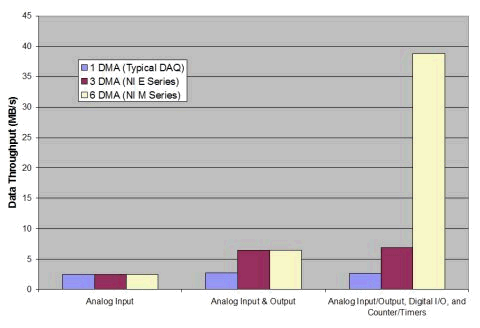
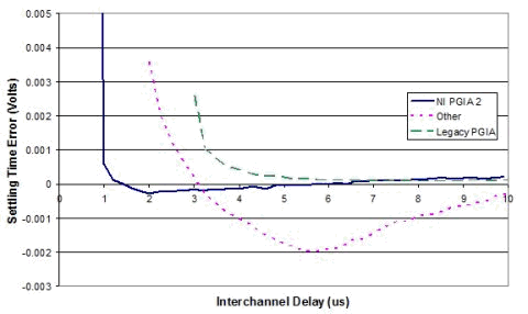
New technologies used in NI M Series DAQ NI's M series data acquisition equipment (DAQ) sets a new standard for data acquisition hardware functions with a new revolutionary architecture. In addition to integrating the most advanced technologies on the market, these devices also absorb some new design advantages, significantly improving their performance, accuracy and I / O channel density: NI-STC 2-custom timing controller ASIC NI-MCal technology-revolutionary calibration and linearization method NI-PGIA 2 technology customizable gain amplifier NI-STC 2 is an application specific integrated circuit (ASIC) specifically designed for M series DAQ devices. It increases the number of I / O channels per device and increases the overall data throughput rate by 1200%. NI-MCal technology is a linearization calibration tool that provides unmatched accuracy improvements in all input ranges. In addition, NI-PGIA 2's customizable amplifier technology provides a faster sampling rate and higher resolution. NI-PGIA 2 has three versions optimized for cost, speed, and accuracy. Figure 1 The new M-series technology provides higher performance, more I / O numbers and greater value NI-STC 2 is a customizable ASIC that can control the timing, synchronization, and routing functions of all input and output data acquisition operations. NI-STC 2 provides: 6 DMA channels – each function has a dedicated scatter-gather DMA controller clocked digital I / O (up to 10MHz) Encoder compatible 32-bit counter / timer RTSI bus signal routing for multiple devices Synchronization of internal and external timing signal routing for PLL for clock synchronization Many plug-in data acquisition devices are not limited by their sampling or update rate, but by the speed at which they transfer data to the PC's memory. Older data acquisition devices use interrupt request lines (IRQ) to transfer data from the device to the PC, and jumpers need to be set to avoid memory conflicts. IRQ uses a computer processor to control the data transmission, which will block the operations being processed by other PCs, thereby reducing efficiency. Modern data acquisition devices have on-board direct memory access (DMA) channels that can directly transfer data from the data acquisition device to PC memory without going through the CPU. DMA can transfer data at high speed and make the CPU perform other tasks at the same time. The new generation of data acquisition equipment (including M series equipment) has six DMA channels. Applying this technology to the device system and timing controller of NI-STC 2, only one device can simultaneously perform analog input, analog output, digital input, digital output, and two counter / timer operations; meanwhile, PC The processor can perform other operations, such as data conversion and analysis. Because most other data acquisition devices have only one DMA channel, IRQ must be used to perform two or more operations simultaneously. As the data transfer rate increases and more operations proceed at the same time, these IRQs will begin to occupy PC processor time, slowing down the system and eventually causing buffer overflow errors. The M series DAQ devices use NI STC 2 technology to perform up to six high-speed operations simultaneously, while minimizing errors caused by data loss or buffer overflow errors. In addition to 16 static digital I / O lines, NI-STC 2 also includes up to 32 hardware-timed digital I / O lines that can input or output digital modes at up to 10 MHz. Each signal can be independently set to digital input, static output or wave output. The digital input and output of NI-STC 2 has a dedicated FIFO buffer, and each buffer has a dedicated DMA channel to read and write data to the FIFO and PC memory. You can use line groups to generate or measure 32-bit wide digital patterns. This mode I / O function is very useful for qualitative applications such as reading barcodes or reading analog-to-digital converters (ADC); this function is also required in any application requiring timing accuracy in the order of microseconds . You can also associate digital circuits with other hardware-timed operations (such as analog input, analog output, and counters, etc.) to synchronize multiple operations on the device. In order to correlate signals, NI-STC 2 will arrange an external or internal signal line to provide a single clock source for those related signals. All M series DAQ devices include two 32-bit counters / timers for pulse generation and frequency measurement. Compared with the conventional 24-bit count / time register, M series devices have 256 times the measurement capacity. In addition, compared with the 20 MHz time base frequency common on older data acquisition equipment, the 80 MHz time base frequency on the board improves the pulse measurement accuracy by 400% and allows higher-speed waveforms to be measured. Based on this counter, you can use quadrature encoders or double pulse encoders for position measurement, or X1, X2, and X4 angle encoders for angle measurement. NI-STC 2 generates multiple time base frequencies by dividing the 80MHz main frequency. These signals can be used internally as clock sources for analog input, analog output, digital I / O, and counter / timers. Each M series device can also generate its own 10MHz reference clock from this 80MHz clock to synchronize multiple devices. This 10MHz reference clock can be connected to other devices in the same system via the RTSI bus. Traditionally, using the RTSI bus to synchronize devices will limit the maximum clock frequency rate of each device to 10 MHz. M-series devices that use NI-STC 2 technology have a phase-locked loop (PLL), which allows each device in the system to synchronize its own 80MHz base frequency to a 10MHz main frequency. With this technology, all devices can not only synchronize to the same main frequency, but also take advantage of the faster 80MHz timing signals generated on the board. Electronic components such as ADCs and programmable amplifiers have nonlinear characteristics and drift due to time and temperature. To compensate for these inherent errors, self-calibration of the device is required. Old-fashioned data acquisition equipment uses a precise reference voltage on the board to make two-point corrections within a certain measurement range. This method cannot avoid the nonlinear error of the ADC component itself, thus reducing the measurement accuracy of the device. In addition, this method can only be calibrated within a certain input range, so for multiple channels with different input ranges, the measurement accuracy will be limited by the tolerance of the resistance network. M-series devices use NI-MCal technology. This is a linearization and calibration engine (patent pending) that can calibrate thousands of voltage levels across all input ranges. NI-MCal uses pulse width modulation (PWM) and high-precision reference voltage together. The duty cycle of PWM is used to change the level so that it can perform self-calibration at multiple points. Calibration parameters are generated and stored in the on-board EEPROM to simulate the nonlinear characteristics of the ADC components and correct subsequent measurement tasks. Compared with the traditional two-point calibration, the implementation of NI-MCal technology improves the measurement accuracy by as much as 5 times. In addition, most M series devices have improved the reference accuracy, and increased the recommended calibration interval from one year to two years, thereby reducing the maintenance cost of the device. M series Vintage E series Calibration type Polynomial calibration, all input ranges Linear calibration, one input range Typical self-calibration time 7 seconds 30 seconds Calibration interval requirements Two years One year When the ADC quickly scans multiple channels, its settling time will greatly affect the conversion accuracy. The so-called settling time refers to the time required to amplify a signal to achieve a specific measurement accuracy standard. If the amplifier does not have a sufficiently short settling time, the quantification of the measured signal will be inaccurate. Shorter settling time allows higher speed sampling while ensuring accuracy. Therefore, for any given resolution or accuracy, a shorter settling time is required. To ensure measurement accuracy, NI introduced custom NI-PGIA 2 technology when designing M series devices. The NI-PGIA 2 technology in each device of the M series is optimized for cost, speed, and accuracy. For example, NI-PGIA 2 technology in high-precision M-series devices is optimized for short settling time, low noise, and high linearity of 18 bits. NI-PGIA 2 technology can ensure the specified resolution of the device at the maximum sampling frequency by minimizing the settling time, thereby improving accuracy. Figure 4 shows that the high-speed M-series NI-PGIA 2 can achieve imaginary zero errors in 1.5 µs at 20 V (the worst case). M series devices have added some additional functions for plug-in data acquisition to improve measurement accuracy and safety, and are easy to use. Although 12-bit and 16-bit data acquisition devices have become the current measurement standard, M series devices have 18-bit resolution. The smallest voltage change that an 18-bit ADC can detect is only 1/4 of a 16-bit device and 1/64 of a 12-bit device. These 18-bit devices also contain a programmable low-pass filter to avoid quantization of high-frequency noise. The digital lines of M series equipment have overvoltage, low voltage and overcurrent protection devices, which can avoid damage to the equipment and PC when excessive signals are accidentally added to the digital lines. In addition, there are often digital bounces in industrial relays and switches, and input filters in counter / timer circuits can avoid this phenomenon. Digital protection and counter / timer line filters are particularly useful for industrial and control applications. All M series devices have NI-DAQmx measurement service and driver software. NI-DAQmx brings unprecedented improvements to the productivity and performance of data acquisition. The integrated DAQ assistant provides a step-by-step wizard tool to help configure, test, and program measurement tasks. In addition, NI-DAQmx supports multi-threading, so that multiple operations can be performed simultaneously on a single processor. M series DAQ devices can work seamlessly with IEEE 1451.4 smart sensors. You can use M series DAQ equipment, NI signal conditioning and NI-DAQmx measurement service software to read the smart sensor data. This eliminates the need to manually input sensor data. Instead, it can automatically read the sensor's spreadsheet and use it to calibrate sensor measurements. Table 2 summarizes the differences between NI's M series and old E series DAQ devices. M series E series Analog input aisle 16 or 32 16 or 64 Sampling rate Up to 1.25 MS / s (16 bits) Up to 1.25 MS / s (12 digits) Resolution 16 or 18 bits 12 or 16 bits Calibration method NI-MCal (applies to all ranges) Linear two-point type (try a single range) Programmable low-pass input filter There is 1 no Analog output aisle 0, 2, or 4 0 or 2 Update rate Up to 2.8 MS / s, 16 bits Up to 333 kS / s, 16 bits Resolution 16 bits 12 or 16 bits Output range Programmable per channel 1 ± 10 V, 0 to 10 V Output offset Programmable per channel 1 0 V Digital input / output line 24 or 48 8 or 32 rate 10 MHz, clock synchronization 1 Software timing Related Digital IO Have no Line protection Improved overvoltage / low voltage protection and overcurrent protection — counter line 2 2 Resolution 32 bit 24-bit Counter base frequency 80 MHz 20 MHz Quadrature encoder input Have no Counter debounce filter Programmable per line no system Clock synchronization PLL, RTSI RTSI DMA channel 6 1 or 3 Connector type VHDCI (High Density) SCSI II 1 Limited to certain M series devices Table 2 Functional differences between M series and E series DAQ devices With the introduction of M-series devices, NI has been expanding its functions while reducing the cost of data acquisition. Among them, OEM customers will be very grateful for the extended I / O function of M series devices, because it has reduced the unit price per I / O channel by more than 30%. NI-STC 2, NI-MCal and NI-PGIA 2 technologies provide functions not previously available in plug-in DAQ devices, and the M series can be seamlessly combined with the NI LabVIEW graphics development environment and NI-DAQmx measurement service software to Provide better performance, higher value and more I / O.
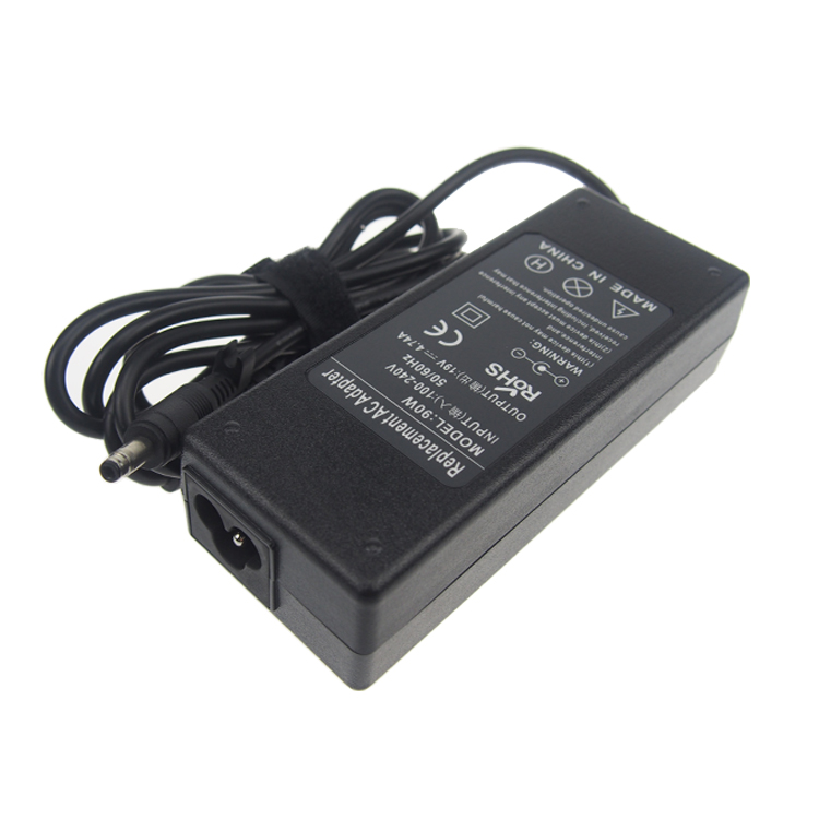
The LG
Laptop Charger is specially
designed for your LG notebook to recharge the battery. Yidashun can offer a
full range replacement LG power
Adapter for laptop with best service at the
lowest cost.
All our LG Laptop Charger are Brand New Replacement Product, works as Genuine parts, 100% OEM Compatible!!
Our adapter with smart IC to protect your laptop with over current protection,
over load protection, short circuit protection, over heat protection.
If your original LG laptop charger is not work anymore, please tell us your laptop
model, we will help select the correct OEM replacement models for you. we offer a full 1
year warranty for our adapters.
LG Laptop Charger,LG Battery Charger,LG Laptop Tablet Charger,LG Laptop Battery Charger Shenzhen Yidashun Technology Co., Ltd. , https://www.ydsadapter.com

Figure 2 NI-STC 2 has 6 DMA channels, which can greatly improve the data throughput rate 
Figure 3 M series devices generate an onboard 80MHz frequency and a PLL to synchronize multiple devices
Table 1: Comparison of calibration between M series and E series 
Figure 4 NI-PGIA has a shorter settling time than traditional products ![]()
![]()
![]()
![]()
![]()
![]()
![]()
![]()
![]()
![]()
![]()
![]()
![]()
![]()
![]()
![]()
![]()
