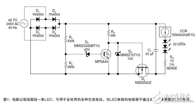
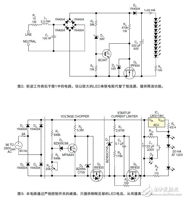
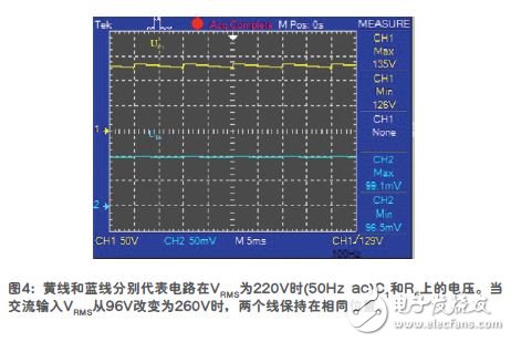
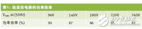
For LED driving, the constant current method is better than the constant voltage method. In the circuit proposed in this paper, the constant voltage regulator commonly used for LEDs is replaced by a constant current source. In addition, a starting current limiter is used to suppress large inrush current, and the voltage chopper can be used for AC input voltage range as wide as 96VRMS ~ 260VRMS. The concept of this article comes from two design examples published in 2011 (Reference 1 and Reference 2), which have been improved to improve power efficiency at low cost. The circuits in Figure 1 and Figure 2 share the same non-inductive chopper and have controversial power efficiency issues. In order to improve power efficiency, the following two principles should be followed: the heat consumption of the chopper resistor should be as small as possible; the chopper should be switched at the appropriate threshold voltage VTH. In addition, VTH should be as close as possible to the operating voltage of the LED string. This method reduces the power consumption of the constant current regulator (CCR) as much as possible while maintaining a constant LED current. The circuit in Figure 3 is an example that follows the above principle, and the power efficiency is about 85%. The regulator IC1 and R5 form a 20mA CCR. The LED string contains a sufficient number of LEDs and requires a voltage of 120 V at 20mA. Provides a method of indirectly measuring LED current. VTH is the output voltage of the full-wave rectifier bridge, which is divided by R1 to R3 and exceeds the 68V bias of D5, turning Q 1 on and Q 2 off. When Q 2 is on, C 1 quickly charges to VTH, and then slowly discharges through the LED string until the next half cycle of the AC line. At the end of C1 discharge, VTH must not be lower than the 120V voltage required to maintain LED operation, nor can it exceed 1.414 times the minimum AC level VRMS. When the LED requires a voltage of 120V, the 3V input-output voltage difference required by IC1 is added, plus the 1.25V voltage of R5, so the minimum C1 voltage will be 124.25V. For simplicity, this figure is rounded to 125V . As shown in Figure 4, during a 50 ms half cycle of 10 ms, the discharge time of C 1 is much longer than the charging time. During this period, the peak-to-peak value across C 1 is approximately 20 mA & TImes; 10 ms / 22 μF = 9.09 V. Therefore, UC1-MAX = 125 V +9.09 V = 134 .09 V. For simplicity, this value is rounded to 135 V. This value is VTH. Any voltage greater than this value will turn on Q 1 and cut off by Q 2 . When Q 1 turns on, the power consumption of R 4 at 260 VRMS input in Figure 3 is less than 20mW, while the power consumption of the R 1-R 2- R 3- D 5 voltage divider is less than 100mW. This is comparable to the 2.4W power consumption of the LED This result is almost negligible. These resistors have large values, so power consumption is low. R3 is used to precisely adjust VTH to match the actual voltage drop across the LED string. There is a starting current limiter in the circuit to limit the inrush current through C1 and Q2. The inrush current appears in the period just before VTH is reached, just when AC is added. The current limiting resistor reduces the efficiency of each cycle, and R9 only limits the power-on surge to 1.35A until C2 is charged enough to turn on Q3. When the AC input increases, the power consumption of the chopper increases slightly, while the power efficiency decreases slightly, as shown in Table 1. This improved circuit can work from 96 V to 260 Vac (50 Hz). For larger LED currents, it is recommended to increase the capacity of C1 and reduce the resistance of resistor R5. If the LED operating voltage is different, some parameters should be recalculated, the calculation method is the same as above. The lower the LED operating voltage, the lower the AC input voltage. This design example can also be applied to 60Hz alternating current. Author's Note: 1. Use high-current through-hole resistors, or several surface-mounted resistors connected in series. The voltage to be able to withstand is at least 400V. Considering the safety issues during short circuit, it is recommended to use a fuse. 2. Safety warning for novice experiments: There is a lethal voltage in this circuit, and special care should be taken during testing and use. If possible, use an isolation transformer to suspend the AC input of the circuit in the ground, not the oscilloscope chassis. The oscilloscope ground is not isolated, so it cannot be connected to the circuit. 3. Do not press the button when AC voltage is applied. To ensure safety during maintenance, the button causes C1 to completely discharge through R10 to D8. This Automation curtain is specially designed for automation industry. SDKELI LSC2 light curtain is designed for automation field, with small size, compact structure and strong anti-interference ability, and the product meets IEC 61496-2 standards. The Automatic Light Curtain is with reliable quality and very competitive price. It has been used in many factories and has replaced curtains from Sick, Omron, Banner, Keyence, etc. Automatic Light Curtain,Laser Light Curtain,Automation Light Beam Sensor,Automatic Infrared Beam Sensor,Infrared Beam Curttain Sensor,Infrared Beam Sensor Jining KeLi Photoelectronic Industrial Co.,Ltd , https://www.sdkelien.com