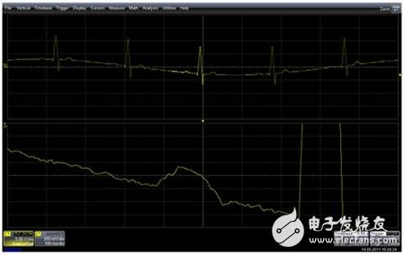
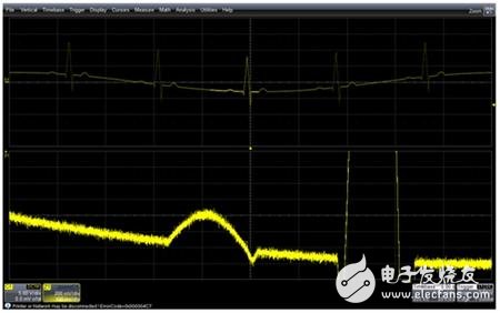
Overview The global medical electronics market is huge and has grown rapidly in recent years. Medical electronic devices range from extremely complex medical imaging systems (such as MRI: magnetic resonance imaging equipment) to simple household electronic blood pressure monitors. Manufacturers engaged in the production of medical electronic devices certainly hope that the higher the measurement accuracy of medical equipment, the better, but the reality is that the precise measurement of various indicators of the human body itself is extremely challenging. When testing electronic devices under experimental conditions, engineers often input known test signals into the device. The test signals themselves are simulated real signals and then observe the response output of the device under test. This method is also suitable for testing medical electronic devices or equipment. However, when medical electronic equipment is used in actual testing occasions, the signal needs to be obtained from the human body itself, and the problem becomes complicated. The problems are: 1. There is no strictly repetitive (periodic) signal source. For example, each heart pulse and each neuron electrical pulse is slightly different from the previous one, and there is no way to repeat it completely. 2. Normally, the SNR (signal-to-noise ratio) of human body signals is not as ideal as other types of electrical signals. However, in medical equipment, the accuracy of the measurement is crucial. From the point of view of test and measurement, when the noise level is large, the test instrument is best able to capture and measure the "single" signal very accurately (rather than the average of multiple signals, because the signal is not repeated). Generate test signals Before a medical instrument product is actually used in a clinic, it undergoes a series of tests during its research and development stage. Even during the product design stage, it is necessary to simulate some signals to test the instrument. These signals are the simulations that the instrument will eventually capture. Human signals to ensure that medical instruments can work properly before delivery to the end user. The upper waveform in Figure 1 shows a test signal. The signal is acquired by a digital oscilloscope (DSO). The signal contains a series of pulses. Each large amplitude pulse has a small amplitude pulse before and after it. The entire waveform reproduces an electrocardiogram (EKG) detection The output waveform of the instrument. The larger pulse is called "R wave", the smaller pulse before the R wave is called "P wave", and the entire pulse sequence is loaded on the slowly changing modulation signal. This signal is collected by the oscilloscope and then output by the ArbStudio Arbitrary Waveform Generator provided by Teledyne LeCroy. ArbStudio can generate almost any arbitrary waveform or standard function waveform (sine, triangle, ramp, etc.) Figure 1: The upper curve is a waveform generated by an ArbStudio arbitrary waveform generator and collected by an 8-bit oscilloscope. The lower paragraph is an enlargement of the upper waveform On ArbStudio, the waveform can be selected for single, multiple, or continuous loop output. Users can also edit and modify real waveforms: for example, adding or deleting noise signals, adding glitch signals, etc. ArbStudio is very suitable for the application in the generation of complex waveforms, or occasions that need to simulate the real acquired waveforms (playback acquired waveforms). Teledyne LeCroy provides two arbitrary waveform generators-ArbStudio is suitable for applications requiring long storage and complex waveforms; WaveStaTIon is suitable for applications with shorter storage and generating simple function waveforms. Perform measurement work If it is assumed that the small "pulse" (P wave) of the ECG signal above is the part that we are interested in and need to measure, the lower curve in Figure 1 is the waveform after the P wave is amplified, that is, the highlighted part of the upper waveform. If you want to measure the level of noise in the signal for this protrusion, then this signal is typical. In addition, the oscilloscope provides parameters for measuring peak-to-peak and noise RMS values. However, if the part to be measured is the base value of the signal itself, or the baseline of the signal has been submerged in noise, how should we measure it? Since the signal itself is non-periodic, the method of using average filtering will certainly not work. Another way to reduce noise is to use filters. In this example, the frequency of the noise signal is much higher than the frequency of the signal part of interest, so a low-pass filter can be applied. Many digital oscilloscopes have their own low-pass filters. Teledyne LeCroy provides Digital Filter Package (DFP), users can choose to use different types of filters such as low pass, high pass, band pass, band stop, etc., and can customize the cutoff frequency. In addition, users can use the mathematical algorithm of LeCroy's own oscilloscope, which is also a limited impulse response digital filter, known as ERES (Enhanced ResoluTIon), which can help us remove high-frequency components in the signal. Oscilloscopes from other manufacturers also provide a built-in filter, usually in Hi-Res mode, but users cannot control the filter parameters in this mode. The signal in Figure 2 is exactly the same as in Figure 1, but with Hi-Res mode, the noise level is greatly reduced. However, the general shape of the waveform also changed a lot. Therefore, this "simple and rough" way of filtering noise is not suitable for the signal. Figure 2: The signal in the figure is the same as that in Figure 1, which is collected with an 8-bit oscilloscope, but the Hi-Res mode is adopted, which reduces the noise level of the signal, but also brings a lot of distortion to the signal The signal in Figure 3 was acquired using a higher resolution oscilloscope, HDO (High DefiniTIon Oscilloscope). HDO uses a lower noise front-end amplifier to reduce the noise of the signal introduced by the oscilloscope itself, and uses a 12-bit resolution ADC to quantize the signal. Figure 3: The same signal is acquired using an HDO oscilloscope, and the noise level after the amplified waveform is significantly lower than that of an 8bit oscilloscope Compared with the traditional 8-bit resolution oscilloscope, although the waveform in Figure 3 still appears to be noisy, the noise level is much lower than the signal in Figure 1, and the signal in Figure 3 is very close to the shape of the original signal . In Figure 1, most of the noise we see is due to the use of low-resolution oscilloscopes. In Figure 4, we use a filter to further reduce the noise of the collected signal, so that the user can see the "baseline" of the signal itself, and then we can find a very interesting phenomenon is that there is an obvious drop at the end of the P waveform Punch, and this undershoot is very meaningful for clinical medical diagnosis. Figure 4: Using a high-resolution HDO oscilloscope allows us to see the "baseline" of the signal itself to sum up Testing medical electronic equipment often requires the acquisition and measurement of a single captured signal, and these signals generally contain a lot of noise. When we measure the indicators of these devices, we need to know the noise level of the signal itself, rather than collecting Noise added during the process. Based on this, Teledyne LeCroy provides a 12-bit high-resolution oscilloscope HDO, which is very suitable for this type of application. Moreover, ArbStudio, an arbitrary waveform generator, is also very suitable for simulating real human signals. Engineers can even collect real human signals through HDO and then use ArbStudio to play back these signals.
Sweet safe packing are available Covered Copper Wire,Film Covered Flat Copper Wire,Non Woven Covered Copper Wire,Polyester Film Covered Copper Wire HENAN HUAYANG ELECTRICAL TECHNOLOGY GROUP CO.,LTD , https://www.huaonwire.com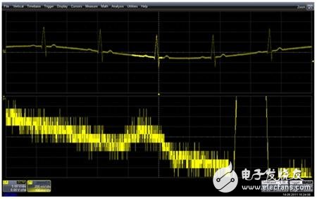

About Film Covered Flat Copper Wire
1) Polyester Enameled Aluminum Wire, class 130
2) Modified polyester enameled aluminum wire, class 155
3) Polyesterimide enameled aluminum wire, class 180
4) Polyester (imide) coated with polyamide-imide enameled aluminum wire, class 200
5) Polyimide enameled aluminum wire, class 220

• Professional production and sales Team
• Double or Three Type Insultaions covered wires