With the development of social economy and the improvement of people's living standards, cars have gradually entered the family, and how to effectively prevent the theft of cars has also become a concern of car owners. At present, among automobile anti-theft devices, ordinary electronic remote control anti-theft devices occupy a large market share due to their low prices. But ordinary electronic remote control anti-theft devices are mostly fixed carrier frequency communications, which are easy to be interfered, intercepted and cracked. It is reported that the general remote control lock can be copied by a dedicated decoder within 30s, and can be cracked within 1min. Ordinary electronic remote control anti-theft devices are mostly one-way communication. The car owner can remotely lock and unlock the car, but the car information cannot be fed back to the car owner in time.
In response to the deficiencies of ordinary electronic anti-theft devices, we apply the frequency-hopping communication technology used in military communications to the design of automotive intelligent remote control anti-theft devices. In the communication process, the communication frequency of both parties is constantly changed, making it difficult for information transmission to be tracked, interfered with or intercepted, and cracked, which will effectively improve the security and reliability of the anti-theft system.
1 System overall scheme design
The system is composed of two parts: vehicle-mounted terminal and human-held terminal. The vehicle-mounted terminal mainly completes the reception and execution of human-machine control commands, executes the car lock and unlock commands, and completes the detection and transmission of car anti-theft information; the human-held terminal mainly completes the transmission and reception of control commands for the car owner to lock and unlock the car Car-related alarm information and command execution information sent from the vehicle-mounted terminal. The functional structure of the system is shown in Figure 1.
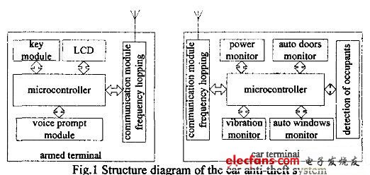
Figure 1 block diagram of the overall structure of the system
2 circuit design and implementation
2.1 Circuit design of vehicle-mounted terminal
The vehicle-mounted terminal mainly completes the monitoring of the anti-theft information of the car and sends the information of the abnormal state of the car to the owner of the vehicle, and receives the control instructions of the operator holding the terminal, such as locking and unlocking the car. The sensor circuit with multiple information fusion is designed to improve the reliability of the anti-theft device by monitoring the doors, windows and car seats. The added backup power management function ensures that the anti-theft device can still work normally when the main power cord is cut. It is mainly composed of the main control MCU module, wireless frequency hopping communication module, car door and window monitoring, power supply monitoring, vibration detection, and whether there are people in the car monitoring module.
2.1.1 Main control MCU module circuit
The main control MCU is mainly responsible for the coordinated control of the entire system, the detection and processing of sensor information, the configuration of frequency-hopping communication modules, and the sending and receiving of information. It is implemented with C8051F340. C8051F340 is a mixed-signal system-level integrated chip from Cygnal of the United States. It has a high-speed CIP-51 core compatible with 8051. It integrates the analog, digital peripherals and other functional components commonly used in data acquisition and control systems. The internal clock frequency can be Reached 48MHz. With enhanced SPI interface, it is convenient to realize the control of nRF905.
2.1.2 Hardware circuit of frequency hopping communication module
The hardware circuit of the frequency hopping communication module is implemented by the monolithic RF transceiver chip nRF905 launched by Nordic. Its power consumption is very low. The current is only 11mA when transmitting at an output power of –10dBm, and the current is 12.5mA in the receiving mode. The transmission distance is greater than 100m. Work on 3 ISM channels at 433/868 / 915MHz (available for free). nRF905 can automatically complete the work of processing the header and cyclic redundancy code verification, and can automatically complete the Manchester encoding / decoding by the on-chip hardware. It uses SPI interface to communicate with the microcontroller. The configuration is very convenient, the performance is reliable, and the artificial carrier frequency can be achieved. Control, with 128 selectable frequency points, the frequency point interval is 100kHz, and the frequency point switching time is 650μs, which can quickly realize the frequency point switching. Using this chip can form a transceiver module for wireless frequency hopping communication. The module circuit and the single-chip interface circuit are shown in Figure 2. The working mode configuration is realized by connecting to the single-chip computer through PWR_UP, TRX_CE and TX_EN. Carrier detection, address detection, and interrupt detection are carried out through CD, AM, and DR. Communication with the microcontroller through the SPI interface enables configuration of carrier frequency, communication command data format, and data reception.
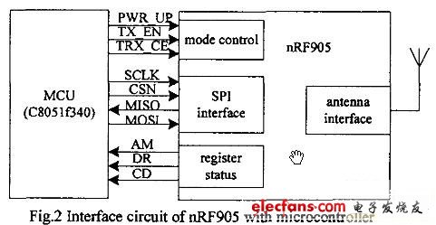
Figure 2nRF905 and MCU interface circuit
2.1.3 Car door and window monitoring module
By placing the photoelectric detection diode at the door and window of the car, when the door or window is not locked, the corresponding photoelectric detection circuit will detect the relevant information, and when there is no one in the car, the car terminal will notify the car micro-processing system through the car main control interface Start the automatic door and window closing circuit, and remind the owner that the door or window is not locked, and the alarm signal is issued when the door and window are opened in the anti-theft state.
2.1.4 Whether there is an unmanned detection module in the car
Through the pressure measuring device designed by the strain resistance placed under the seat of the car, to determine whether there are people in the car, if there is no one in the car, and the car anti-theft lock system is not activated, the automatic lock will be delayed 1min; if the car anti-theft lock is activated, If there is someone, it is possible that someone has stolen the car, and the anti-theft device immediately calls the police.
2.1.5 Outside vehicle vibration detection module
Vibration detection outside the car is used to detect whether someone collides with the car when the car is in the anti-theft state, and alarms if there is. It uses the vibration sensor Z04B, which is a highly sensitive vibration module that can detect extremely weak vibration waves; easy to install, not limited by any angle; good anti-interference, no response to external sounds, anti-lightning and firecracker interference Ability, the output is a transient pulse, used to form a reliable vehicle vibration detection module.
2.1.6 Power measurement and control module
The backup power management function is designed. When the main power of the car is cut off, the backup power supplies power and feeds back the situation to the car owner to improve the security and reliability of the anti-theft system.
2.2 Circuit design of human-held terminal
The human-held terminal completes the transmission of control commands such as locking and unlocking of the car, and receives car-related information from the vehicle, such as vibration information, door and window opening and closing information, and gives voice prompts. It is composed of the main control MCU circuit, frequency hopping communication module and human-machine interface module, in which the main control MCU circuit and frequency hopping communication module are the same as the vehicle terminal.
The human-computer interaction interface module circuit mainly sends out human operation commands by the button circuit. The LCD liquid crystal display circuit is used to make the operation more convenient. The ISD1820 is used to design a voice prompt circuit for alarm prompts and vehicle terminal command execution status prompts.
Portable charger which is also named Power Bank or portable phone charger is popular for charging smart phones and mobile tablet devices. Our portable phone battery charger is compatible with most of the mobile phones in the market . there is no need to worry compatibility if you want to use by yourself or send as a gift .
Provide best power bank.
Perfect compatibility
Our power bank is compatible with most of the mobile phones in the market .
There is no need to worry compatibility if you want to use by yourself or send the Powerbank Phone Charger as a gift.
Share together , more friend ship
Ultra slim and easy to carry
Genuine Portable Battery Mobile Power Bank Charger
Li-Polymer with LED Indicator
Li-polymer battery
Customized the shape
Ultra thin power bank adopts Li-polymer cell inside
High safety performance
Li-polymer cell will not explode
The portable battery charger is designed more friendship , and is Built-in intelligent protect chip to prevent overcharge . we aim to provide the best portable charger for customers .
The advantages of this produce as following :
Ultra thin and easy to carry
High capacity
Dual input & dual output
Dual output more convenient
Both apple and android user can charge and recharge with either micro cable or Lightning Cable .
Power Bank
Power Bank, Power Bank Charger, Powerbank Phone Charger, Power Bank Battery, Portable Battery, Phone External Battery
Hebei Baisiwei Import&Export Trade Co., LTD. , https://www.baisiweicable.com