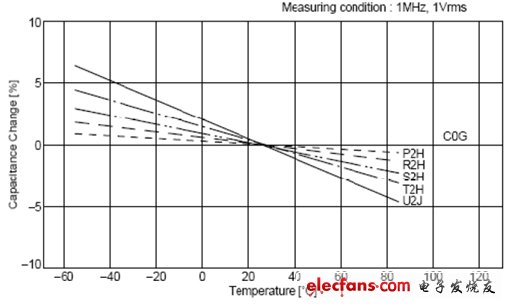
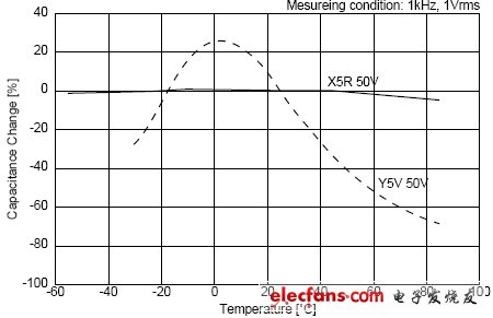
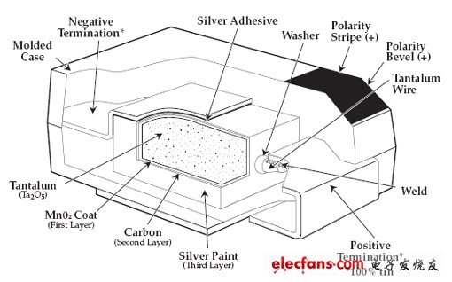
Power is often the most overlooked part of our circuit design process. In fact, as an excellent design, power supply design should be very important, which greatly affects the performance and cost of the entire system. Here, only the capacitor usage in the board power supply design is described. This is often the most overlooked place in power supply design. Many people engage in ARM, engage in DSP, and engage in FPGAs. At first glance, they seem to be very advanced, but they may not be able to provide a cheap and reliable power solution for their systems. This is also a major reason why our domestic electronic products are rich in functions and poor in performance. The root cause is the R&D atmosphere. Most R&D engineers are dry and not practical. The company is only seeking rich functions for short-term benefits, just killing chickens today. No matter whether there is any egg to eat tomorrow, it is not a pity that "the road is hungry and dead." Turning back to the point, let me introduce the capacitor. Most of the concept of capacitors still stays in the ideal capacitor stage. It is generally considered that the capacitor is a C. I don't know if there are many important parameters for the capacitor. I don't know how a 1uF ceramic capacitor is different from a 1uF aluminum electrolytic capacitor. The actual capacitance can be equivalent to the following circuit form: C: Capacitance value. Generally, it is measured at 1 kHz, 1V equivalent AC voltage, DC bias is 0V, but there are many environments where capacitance measurement is different. However, it should be noted that the capacitance value C itself will change with the environment. ESL: Capacitance equivalent series inductance. The pin of the capacitor is inductive. Insensitive to low frequency applications, so it can be ignored. When the frequency is high, consider this inductor. For example, a 0.1uF chip capacitor in a 0805 package has a 1.2nH inductance per pin, then the ESL is 2.4nH. It can be calculated that the resonant frequency of C and ESL is about 10MHz. When the frequency is higher than 10MHz, the capacitance is Inductive characteristics. ESR: Capacitance equivalent series resistance. No matter which capacitor has an equivalent series resistance, when the capacitor operates at the resonant frequency, the capacitive reactance and inductive reactance are equal in magnitude, so it is equivalent to a resistor. This resistor is ESR. There are big differences due to different capacitor structures. Aluminum electrolytic capacitors ESR generally range from a few hundred milliohms to several euros, ceramic capacitors are typically tens of milliohms, and tantalum capacitors are between aluminum electrolytic capacitors and ceramic capacitors. Let's take a look at the frequency characteristics of some X7R ceramic capacitors: Of course, there are many capacitor-related parameters, but the most important ones in design are C and ESR. Here is a brief introduction to the three capacitors we commonly use: aluminum electrolytic capacitors, ceramic capacitors and tantalum capacitors. 1) The aluminum capacitor is made by etching the aluminum foil groove and then sandwiching the insulating layer, and then dip the electrolyte solution. The principle is chemical principle. The capacitor charge and discharge depends on the chemical reaction, and the response speed of the capacitor to the signal is affected by the electrolyte. Moving speed of charged ions The degree limit is generally applied to the filter with low frequency (below 1M). The ESR is mainly the sum of the equivalent resistance of the aluminum crucible and the electrolyte, and the value is relatively large. The electrolyte of the aluminum capacitor will gradually evaporate, resulting in a decrease or even a failure of the capacitor, and the evaporation rate will increase as the temperature increases. For every 10 degrees increase in temperature, the life of the electrolytic capacitor is halved. If the capacitor can be used for 10,000 hours at room temperature of 27 degrees, only 1250 hours can be used in a 57 degree environment. Therefore, the aluminum electrolytic capacitor should not be too close to the heat source. 2) The storage of the ceramic capacitor is based on the physical reaction, so it has a high response speed and can be applied to the upper G. However, the ceramic capacitors vary greatly depending on the medium. The best performance is the capacitor of C0G material, the temperature coefficient is small, but the dielectric constant of the material is small, so the capacitance cannot be made too large. The worst performance is the Z5U/Y5V material. This material has a large dielectric constant, so the capacitance can be tens of microfarads. However, this material is affected by temperature and DC bias (DC voltage will cause the material to be polarized, resulting in reduced capacitance). Let us look at the C0G, X5R, Y5V three material capacitors affected by the ambient temperature and DC operating voltage. It can be seen that the capacitance of C0G does not change with temperature, and the stability of X5R is slightly worse. When the material of Y5V is 60 degrees, the capacity becomes 50% of the nominal value. It can be seen that the 50V withstand voltage Y5V ceramic capacitor has a capacity of only 30% of the nominal value when applied at 30V. Ceramic capacitors have a big drawback, which is fragile. So you need to avoid bumps and try to stay away from the board where the deformation is easy. 3) Tantalum capacitors are like a battery in principle and structure. The following is a schematic diagram of the internal structure of the tantalum capacitor: Tantalum capacitors have the advantages of small size, large capacity, fast speed, low ESR, and the price is relatively high. The size of the tantalum capacitor and the pressure resistance are determined by the size of the raw material powder particles. The finer the particles, the larger the capacitance, and the thicker the Ta2O5 if a larger pressure is required, which requires the use of larger particles. Therefore, it is very difficult to obtain a tantalum capacitor with a high withstand voltage and a large capacity. Another place where tantalum capacitors need to be noticed is that tantalum capacitors are easier to break down and have short-circuit characteristics, and have poor surge resistance. It is very likely that a short circuit will occur due to a large instantaneous current causing the capacitor to burn out. This should be considered when using ultra-capacitance tantalum capacitors (such as 1000uF tantalum capacitors). It can be seen from the above that different capacitors have different applications, and the higher the price, the better.
The Description of 3G Rubber Antenna:
The 3G Rubber Antenna is a multiband Covert Omni Antenna that allows the use of multiple frequency bands with a single antenna. Suitable for Frequencies: HSDPA, UMTS (3G) (1920-2770 MHz), GSM (2G) 900 (824-960 MHz), DCS 1800 (1710-1880 MHz)
3G Rubber Antenna Polarization: Vertical | 3G Rubber Antenna Connector Type: Customized | Impedance:50 ohm | VSWR:2 Input
The Advantage of 3G Rubber Antenna:
1,Rich experience , proven technique
2,Reasonable price
3,Wider frequency
4,OEM/ODM available
5,Perfession servie
6,ISO:9001 certification
7,1 year guarantee
8,Fast delivery time
9,R&D
10,Huge Capacity
3G Rubber Antenna 3G Rubber Antenna,Black Rubber Antenna,Folding Rubber Antenna,Omni 3G Antenna Shenzhen Yetnorson Technology Co., Ltd. , http://www.yetnorson.com