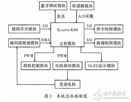
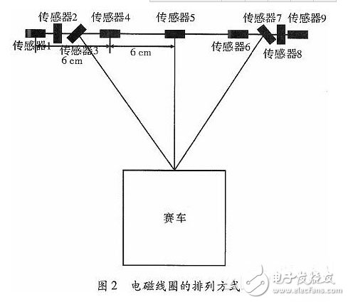
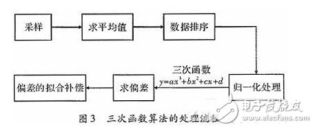
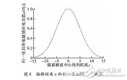
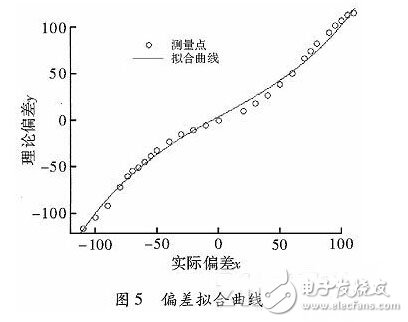
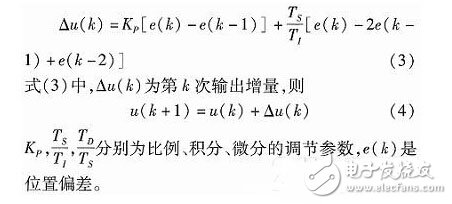
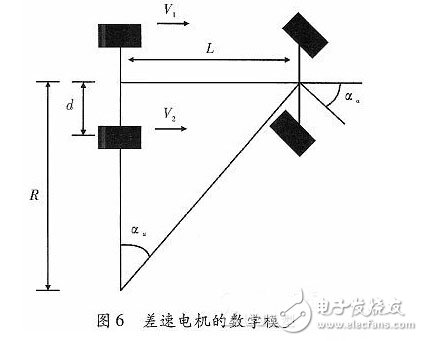
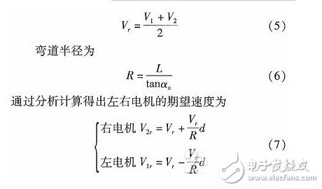
In order to realize the stable and fast automatic hunt of the smart car, the electromagnetic coils arranged in the “five horizontal and two vertical plus eight characters†are used to identify various complicated tracks. The deviation is obtained by the cubic function algorithm, and the differential motor algorithm is used to process the curve, and the function of electromagnetic navigation is realized. Practice has proved that the system can accurately control the smart car to run stably and quickly, and achieve the expected results. The design requirements for the intelligent car hunt road are: a copper enameled wire with a diameter of 0.5 mm is laid in the middle, and the enameled wire has a sine wave signal with a frequency range of 20±2 kHz and a current range of 50-150 mA. With the development of smart cars, it is necessary to adapt to more complicated tracks, such as right angle bends, ramps, obstacles and so on. The smart car designed in this paper is developed based on KineTIs K60 single-chip microcomputer. The electromagnetic coil is used as the inductive sensor. The deviation algorithm is used to control the precise hunt function of the car, so as to realize the intelligent fast and stable hunt driving of the smart car. 1 hardware overall design The intelligent car system consists of nine parts: KineTIs K60 main control module, sensor module, servo control module, motor drive module, OLED display module, dial switch module, encoder speed measurement module, parking detection module and obstacle detection module. The overall framework of the system is shown in Figure 1. In addition to the above 9 parts, there is a power module. The whole smart car is powered by a 7.2 V nickel-cadmium battery. The output of the LM1117 regulator chip output 3.3 V is the main control chip K60, the DIP switch module, the parking detection module, and the OLED display module. . A LV2940 regulator chip is used to supply a 5 V voltage to the sensor module separately. Another LM2940 regulator chip is supplied with a 5V voltage to the Bluetooth debug module, the obstacle detection module, the encoder speed measurement module, and the motor drive module. In addition, it can be found through experiments. The S3010 Futaba servo can directly add 7.2 V voltage, and the response speed of the servo will also increase, so the battery voltage can be directly used as the power supply for the servo. Both the servo control module and the DC motor are driven by 7.2 V. The alternating voltage signal collected by the electromagnetic coil is amplified by the double operational amplifier MAX4451, and the alternating voltage signal is detected by the diode's double voltage detection circuit to form a DC signal, and then collected by the A/D conversion circuit of the single chip microcomputer. It is proportional to the value of the induced voltage amplitude. The smart car works in a dual motor mode, so four BTS7971s are used as the driver chip. The BTS7971 combines a p-channel high-side MOSFET and an n-channel low-side MOSFET with an integrated driver IC to form the half of the H-bridge that can withstand high currents. Therefore, the four BTS7971s can be connected to form two H full bridges, thereby realizing the forward and reverse rotation of the motor. In addition, the 74HC244N three-state eight-buffer isolation motor drive module prevents the interference signal generated by the rotation of the motor from being injected into the main control chip and causing damage. A normally open plastic reed switch is used as the detecting element. A permanent magnet is buried at the beginning and end of the road. When the trolley passes the magnet, the reed switch is closed, and this signal is transmitted to the CPU to realize the parking function. Install two proximity switches on each side of the cart to detect obstacles. Under normal conditions, the two proximity switches are in the off state 0. By adjusting the detection distance of the proximity switch, when the obstacle on one side of the road enters the detection range of the proximity switch, the proximity switch remains in the conduction state 1, and the change of 0 and 1 of the signal is transmitted to the CPU, so that the trolley can be realized. The obstacle detection function. 2 smart car electromagnetic hunt 2.1 Sensor layout structure The electromagnetic coils arranged in "five horizontal two vertical plus eight characters" are shown in Fig. 2. This structure enables the car to run independently and stably in straight, right-angled, S-bend, cross-bend and ramp, and has the characteristics of strong anti-interference, high stability and high mechanical strength. Stable navigation is maintained even at high speeds. 2.2 cubic function algorithm Pre-processing should be performed before using the cubic function algorithm to quickly find the deviation using the cubic function. Preprocessing includes sampling, averaging, data sorting, and normalization. Since the magnetic field strength of different roads will be different, the maximum and minimum values ​​of the road magnetic field strength can be obtained by sampling first, so that the smart car has a wider application margin for different roads and plays an important role in actual production and use. The processing flow of the cubic function algorithm is shown in Figure 3. After the initialization process, the smart car obtains the maximum and minimum values ​​of the magnetic induction voltage of each electromagnetic coil on the track by sampling, so that the system is stored in the arrays ad max[i] and ad min[i] respectively, so that the system can quickly and efficiently from the array. The values ​​in the comparison are compared to achieve normalization. After each magnetic coil collects 5 times of magnetic induction voltage, the average value is obtained by removing the maximum value and the minimum value; this plays a role of software filtering and reduces accidental error. The five average values ​​are successively sorted in chronological order and stored in the two-dimensional array ad3[i][5], so that the data is continuously updated to obtain the weighted average value and reduce the systematic error. Find the weighted average of the average values ​​after sorting, obtain the closest magnetic induction voltage value with the last acquisition, and store the weighted average of each electromagnetic coil in the array ad4[i]; ad4[i] one by one and ad Comparison of max[i] and ad min[i]: when ad4[i]"ad max[i], bead[5]=1.0; when ad4[i]"ad min[i], then ad5[ i]; When ad min[i] "ad max[i], after normalization, e.jpg = d.jpg, and then normalize the magnetic induction voltage value. Normalization simplifies the cubic function algorithm, and the normalized value can be used to facilitate the observation of the relative magnitude of the change in electromagnetic induction during the debugging process. A cubic function algorithm and a fixed slope change fusion method are used. Within a certain range, the deviation of the cubic function calculation is more accurate. Once the range is exceeded, the variation of the "one" word inductance is merged, and the variation of the deviation is linearized as much as possible. The advantage of adopting this method is that the judgment and processing of various corners, especially the processing of right angles, can make the system make judgments stably, accurately and quickly. The relationship between the distance z of each electromagnetic coil offset track center line and the normalized magnetic induction voltage value ad5[i] is as shown in FIG. Suppose the cubic function of the curve is y=ax3+bx2+cx+d (1) In the formula (1), y=ad5[i], where x is the distance of the electromagnetic coil offset track center line, and ad5[i] of the sensors 1, 4, 6, and 9 in Fig. 2 is taken as the y value; It is -12, -6, 6 and 12, whereby the values ​​of a, b, c, d can be solved. After deriving the cubic function of equation (1), y'=3ax2+2bx+c (2) The deviation x is obtained by substituting the values ​​of a, b, c, and d obtained in the above procedure into the equation (2). The deviation between the above theoretical calculation and the actual deviation always has a certain error due to mechanical reasons. In order to reduce the error, the deviation curve fitting step is added. The curve fit is improved by compensating for the bias fit. This greatly reduces the deviation and maximizes the accuracy of the fit. The actual deviation x of the trolley and the theoretically calculated deviation y can be obtained by curve fitting using the Matlab curve fitting toolbox to obtain the corresponding curve fitting equation. The fitting curve of the deviation fitting curve is shown in Fig. 5. 3 smart car speed control 3.1 Incremental PID Control The deviation compensated by the curve fitting described above changes rapidly in real time and can be used for the control of the speed of the trolley. The trolley system adopts the incremental PID control algorithm, which has a simple structure, high adaptability and easy adjustment of parameters. For the control object with inaccurate control model and large parameter variation, this method can obtain satisfactory results. Because the output only has control variables at a time, the fault output can be reduced by simple logic judgment to avoid system failure. The control method is as follows 3.2 Differential motor algorithm In order to make the smart car have better route, faster speed and higher stability when crossing the curve, the car adds the differential motor algorithm to the above incremental PID control algorithm, which is realized by closed-loop differential feedback regulation system. The differential strategy of the car. In order to achieve the purpose of the differential motor, the mathematical model of the differential motor of the trolley is constructed as shown in Fig. 6. Suppose V1 is the left motor speed; V2 is the right motor speed; R is the curve radius; L is the distance between the front and rear wheels, and the steering angle of the optimal path is αu, then the average speed of the car is In this way, the preset desired speed can be adjusted according to the actual situation. The encoder converts the number of gears rotated by the sampling motor into an electrical signal, which can be used as the trigger signal of the single-chip pulse. The single-chip microcomputer can obtain the specific value of the rotational speed by counting the pulse, then subtract the desired rotational speed from the rotational speed, and then multiply the corresponding value. The coefficient gives the duty cycle of the pulse width modulation. According to the deviation of the above-mentioned cubic function fitting, the single-chip microcomputer can increase or decrease the duty-cycle feedback method to realize the acceleration and deceleration control of the motor, thereby realizing the differential operation of the motor. 4 Conclusion This paper introduces a method of processing magnetic induction signals in the process of magnetic navigation of smart cars. The electromagnetic coils arranged by “five horizontal and two vertical plus eight characters†are used to calculate the deviation of the relative path center of the trolley through the cubic function algorithm, supplemented by differential motor. The algorithm maintains a smooth and accurate operating state even at high speeds. Tests show that the algorithm has good real-time tracking and accuracy. Chandelier Floor Lamp,Crystal Chandelier,Luxury Chandelier,European Classic Chandelier GUANGDONG LAVIUS LIGHTING CO., LTD. , https://www.laviuslighting.com