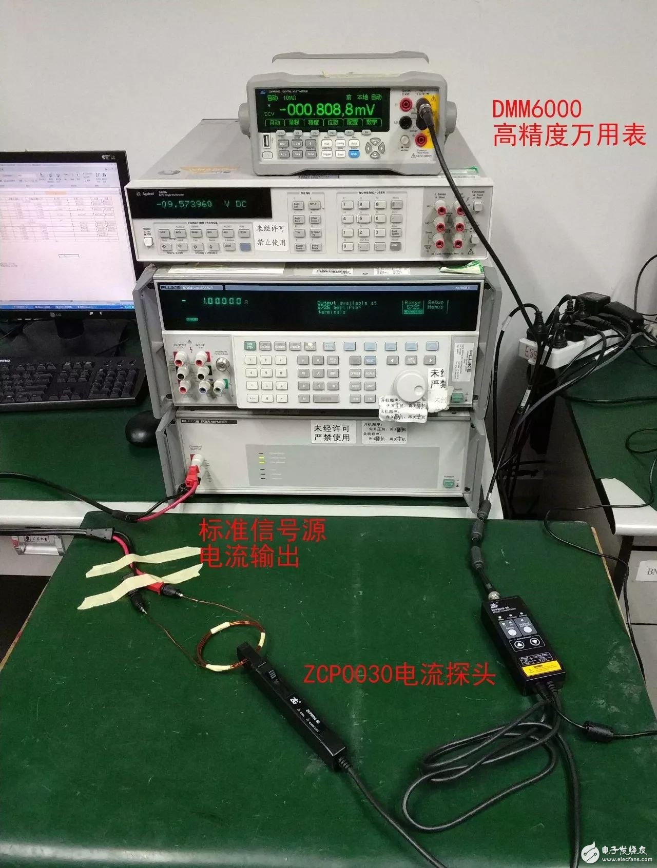
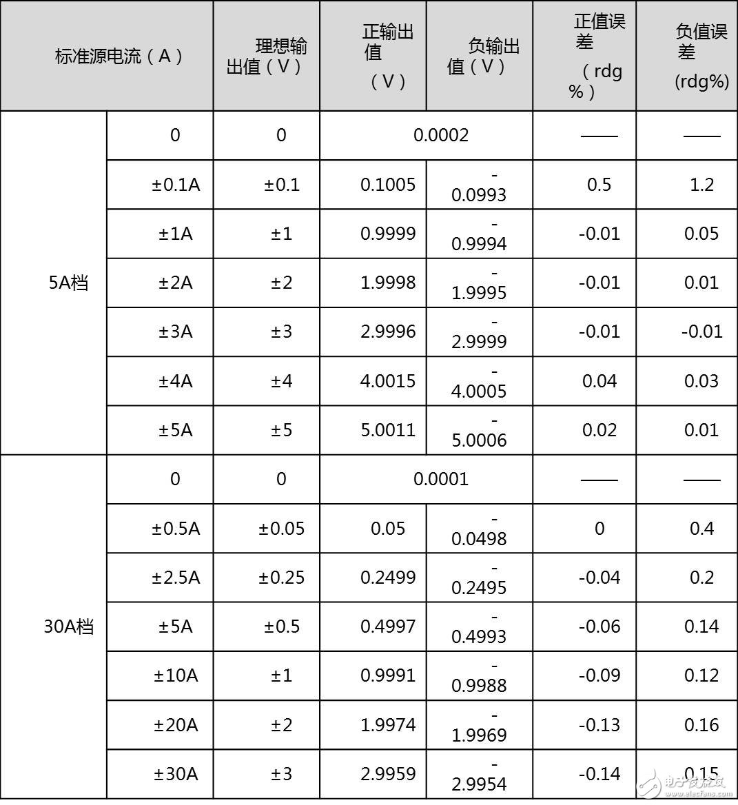
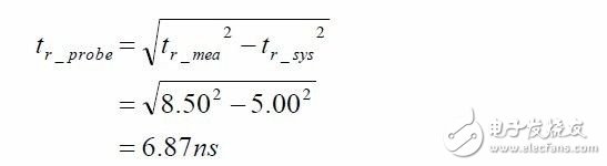
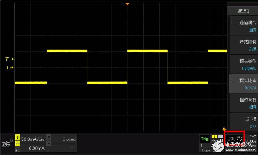
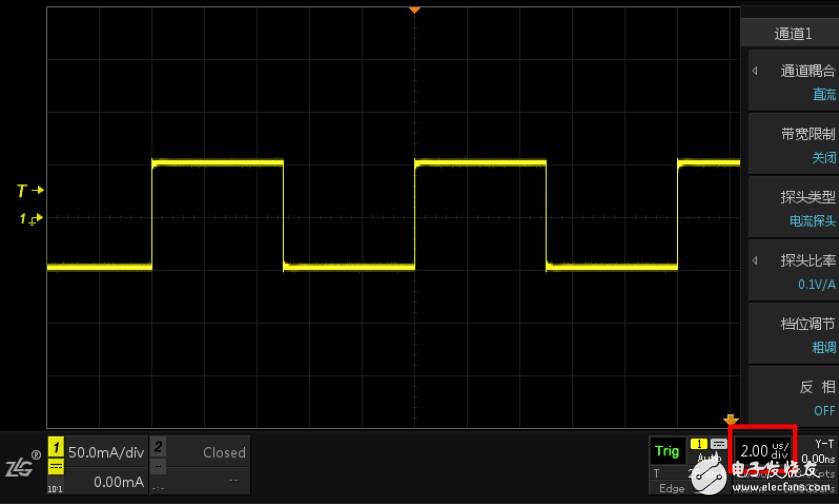
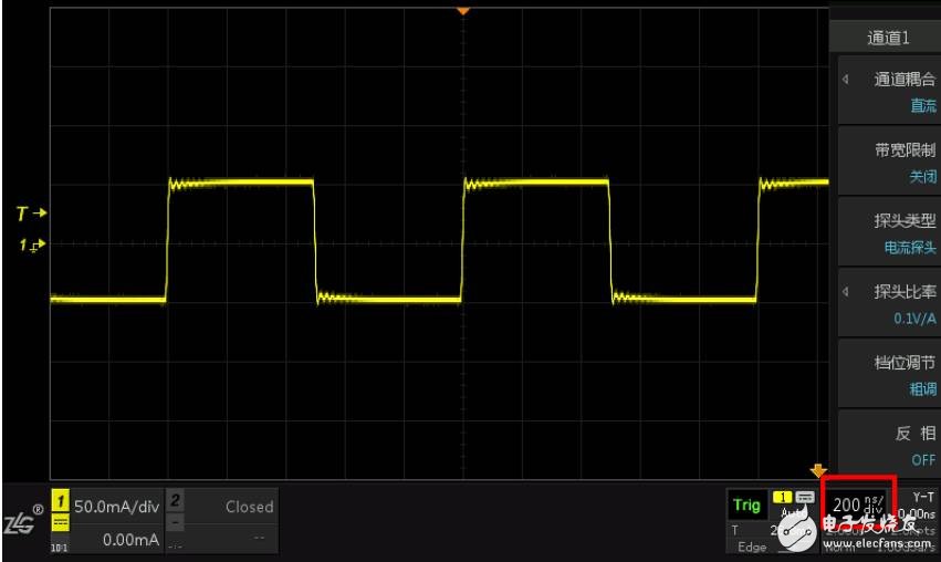
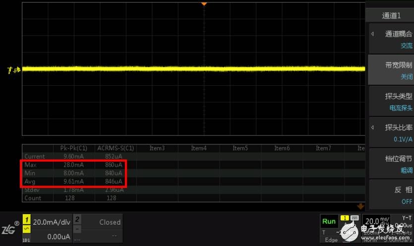
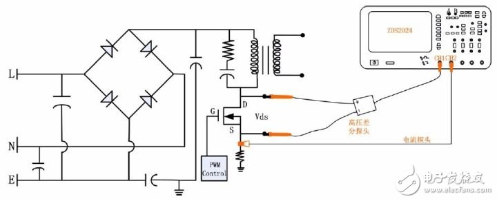
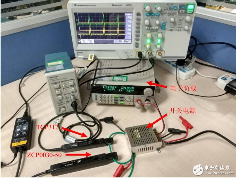
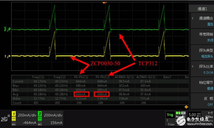
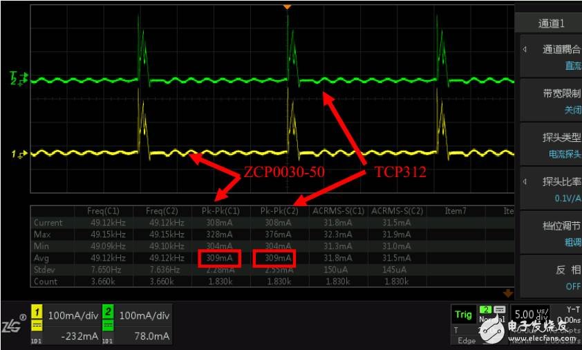
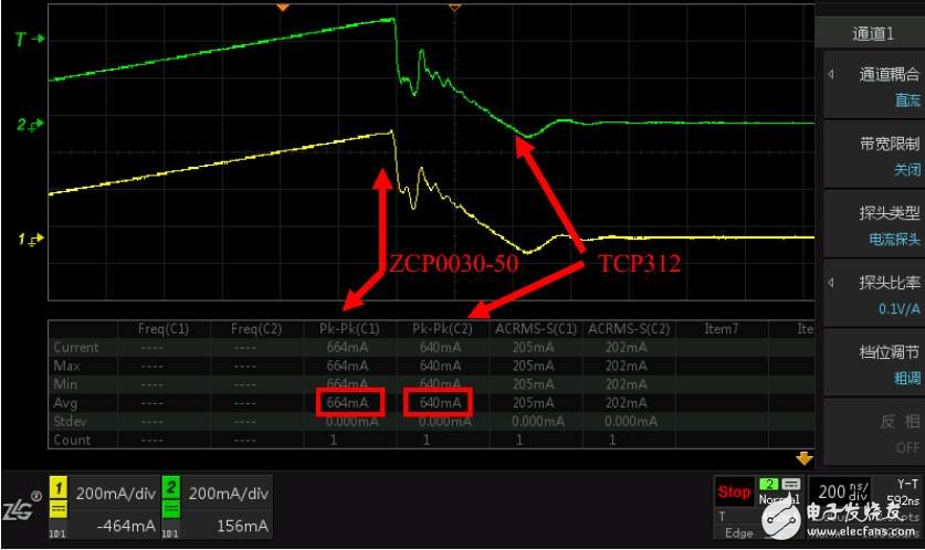
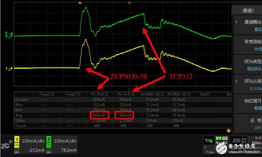
The current probe is an essential accessory for oscilloscopes to measure current, but the price between different brands often varies greatly. What kind of electrical probe is reliable? This article shares the complete process of current probe reliability verification and presents all measured results. You can also verify the current probes you use based on this method. In this paper, the ZCP0030-50 current probe is tested for all-round performance parameters. The main test parameters include DC accuracy, rise time, square wave response, noise, and the current waveform of the switching power supply switch tube. In order to make the measured results more intuitive, we chose T company's TCP312 current probe as the actual measurement comparison, and all the tests are equipped with pictures and test results to ensure the traceability of the test process. First, DC accuracy verification The nominal DC accuracy of ZCP0030-50 is 1% rdg±1mV. The measured accuracy is shown in Table 1. 1, test conditions The test instrument used for the accuracy test is the FLUKE5720 calibrator and the six-and-a-half-digit multimeter DMM6000. In the test procedure, the calibrator FLUKE5720 outputs different measured current values, and the multimeter reads the response voltage value of the current probe. Figure 1 DC precision test environment 2, accuracy data Table 1 DC accuracy test data 3. Verification conclusion The data in the above table shows that the ZCP0030-50 has a DC accuracy within 1% rdg ± 1mV over the range. Second, rise time verification The bandwidth of ZCP0030-50 is 50MHz, corresponding to the rise time ≤ 7ns. The probe rise time refers to the time required for the measurement system response waveform to rise from 10% to 90% of the steady state value during the test pulse. It is a key parameter. The faster the rise time, the faster the response of the probe is. To a more rapidly changing current waveform, the performance of the reduced current waveform is better. 1, test conditions The test instrument used to test the rise time of the current probe is the signal generator Keysight33600 and the oscilloscope ZDS2022. The signal generator produces a square wave with a rise time of 5 ns. The oscilloscope displays the rising waveform and time after passing the current probe. 2, waveform data Figure 2 Rise time of ZCP0030-50 As shown in Figure 2, the rise time measured by the oscilloscope is 8.5 ns. This total time is the rise time of the signal generator itself plus the rise time of the probe. Therefore, the rise time of the probe actually needs to subtract the total time from the signal. The rise time of the generator itself, the specific calculation formula is as follows. 3. Verification conclusion The measured results are within the theoretical calculation range, the rise time is normal, and the measured bandwidth is above 50MHz. Third, square wave response verification The square wave response is mainly used to test the amplitude-frequency response characteristics of the current probe. The current probe can completely reproduce the square wave waveform without distortion, indicating that the probe's amplitude-frequency response is flat and good. 1, test conditions When testing the square wave response of a current probe, the test instrument used was the signal generator Keysight33600 and the oscilloscope ZDS2022. The signal generator generates a square wave with a peak-to-peak current of 100 mA and a frequency of 1 kHz, 100 kHz, and 1 MHz, and the oscilloscope displays the corresponding square wave waveform. 2, waveform data As shown in Fig. 3, when testing the 1KHz current square wave, the square wave response of the probe is very good, the waveform is basically not distorted, the waveform is relatively flat, and no tilt occurs. Figure 3 1KHz current square wave response As shown in Figure 4, when testing a 100KHz current square wave, the square wave response of the probe is very good, the waveform is basically not distorted, the waveform is relatively flat, and no tilt occurs. Figure 4 100KHz current square wave response As shown in FIG. 5, when testing a current square wave of 1 MHz, the waveform of the overall square wave response of the probe is substantially undistorted, the waveform is relatively flat, and no tilt occurs. Figure 5 1MHz current square wave response 3. Verification conclusion The measured results are within the theoretical calculation range, and the amplitude-frequency response is flat . Fourth, noise evaluation Noise is an important parameter of the current probe. The size of the noise directly affects the resolution of the probe. The smaller the noise, the higher the resolution. 1, test conditions The noise test is mainly to use the oscilloscope ZDS2022 to observe the test and record the corresponding test value. 2, accuracy data As shown in Figure 6, the actual noise of the tested current probe has a peak-to-peak value of less than 10 mA and an AC rms value of less than 1 mArms. Figure 6 noise test 3. Verification conclusion The measured results are within the theoretical calculation range and the noise control is good. Five, switching power supply waveform measurement The oscilloscope current probe is mainly used to observe the current waveform on the circuit with the oscilloscope. For example, the current waveform on the MOS tube is convenient for the engineer to debug the circuit and find the circuit problem. ZCP0030-50 and T Company's TCP312 were compared and tested by measuring the current waveform on the switching power supply switch tube to further verify the performance. Figure 7 Current probe test switch tube current connection diagram 1, test conditions The main test instruments used in the current waveform comparison test are: ZDS2022 oscilloscope, electronic load, switching power supply, current probe ZCP0030-50 and TCP312. The test steps are as follows: (1) After the current probe ZCP0030-50 and TCP312 are demagnetized and zeroed, the two probes are simultaneously clamped to the lead wire drawn between the DS poles of the MOS tube, and the BNC outputs are respectively connected to the channel 1 and channel 2 of the oscilloscope. Specifically, as shown in Figure 8. Figure 8 Instrument connection of the switch tube current waveform comparison test (2) Connect the output of the switching power supply to the electronic load, and supply power to the switching power supply. The electronic load can be set to no-load or full-load state, and observe different current waveforms on the MOS tube under two different loads. 2, comparison test As shown in Figure 9, when the switching power supply is fully loaded, the current probes ZCP0030-50 and TCP312 can completely measure the current waveform on the MOS tube. Since the TCP312 bandwidth is 120MHz, the peak-to-peak value of the two has a difference of about 4%. As shown in Figure 10, the current waveform measured by the current probe in the case of a no-load switching power supply. Figure 9 Current waveform between DS poles of MOS tube at full load Figure 10 Current waveform between DS poles of MOS tube at no load The switching frequency of the switching power supply is not very high, about 100KHz, but the rise time of the instantaneous change is at the ns level, and a high bandwidth current probe is required to completely reproduce the current waveform details. When the switching power supply is fully loaded, the current waveform is amplified, and the waveform details at the rapid change of the current are observed. The waveforms displayed by the two probes are almost the same, as shown in FIG. In the case where the switching power supply is unloaded, as shown in FIG. Figure 11 Detail of the current waveform between the DS poles of the MOS transistor at full load Figure 12 details of the current waveform between the DS poles of the MOS tube at no load 3. Verification conclusion For high-frequency noise, the small difference in measured results is due to the difference in bandwidth, but for signals with a switching frequency of only a few hundred KHz, the difference in bandwidth has little effect on the experimental results. It is recommended to choose 50M bandwidth here. Sixth, the final summary In general, DC accuracy, rise time, square wave response, noise, and switching power supply switching tube current waveforms and other angles can be fully tested to verify the overall test results. If you want to actually experience the ZLG Zhiyuan electronic ZCP0030-50 current probe, please contact us at 4008884005, and you are welcome to leave a message directly on the WeChat background. 48V30Ah Lithium Ion Battery,Long Cycle Life 48V 30Ah Battery,48V 30Ah Battery For Vehicle,Deep Cycle Life Battery Jiangsu Zhitai New Energy Technology Co.,Ltd , https://www.jszhitaienergy.com