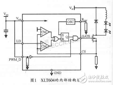
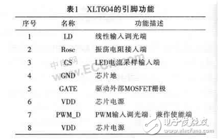
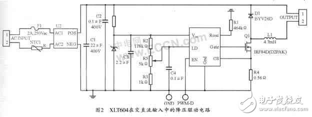
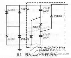
introduction LEDPA is widely used in indicator lights, large billboards, scanners, fax machines, mobile phones, automotive lights, traffic lights, etc. due to its long life and low power consumption. However, in terms of illumination sources, current LEDs do not have the conditions to replace other light sources due to brightness and price. However, as brightness continues to increase, LEDs will replace incandescent and fluorescent lamps in the near future. And the price will also decline due to advances in mass production technology, and application demand will increase substantially. 1 XLT604 chip structure and function The XLT604 is a PWM high efficiency LED driver control chip designed in BICMOS technology. It effectively drives high-brightness LEDs from an input voltage range of 8V (DC) to 450V (DC). The chip can drive an external MOS-FET at a fixed frequency up to 300 kHz, and its frequency can be programmed by an external resistor. The externally highlighted LED string can be controlled in a constant current mode to maintain constant brightness and enhance the reliability of the LED. The constant current value can be determined by the external sampling resistor value, which varies from a few milliamps to 1 amp. The LEDs driven by the XLT604 can be linearly adjusted by an external control voltage, or the brightness of the LED string can be adjusted by an external low-frequency PWM. The internal structure of the XLT604 is shown in Figure 1. The main functions of each pin are listed in Table 1. 2 XLT604 application circuit The XLT604 is a control chip that can step down, boost, and buck-boost high-power LED strings. The chip is suitable for both AC input and DC input of 8-450 V. In the case of AC input, a passive power factor correction circuit can be added to the line to improve the power factor. The XLT604 can drive hundreds or thousands of LEDs in series or in series, and can adjust the constant current value to ensure LED brightness and extend life. The PWM_D terminal can adjust the LED brightness by low-frequency pulse width modulation. At the same time, it also serves as the enable terminal. When the terminal is suspended, the chip has no output control. In fact, the chip can also adjust the brightness of the LED through the linear voltage regulation of the LD terminal. Figure 2 shows a typical application circuit for the XLT604 in AC and DC inputs. 3 parameter design of circuit components 3.1 Calculation of circuit switching frequency The switching frequency determines the size of the inductor in the circuit. Larger frequencies can use smaller inductors, but this increases the loss of the circuit. The typical frequency should be around 20 to 150 kHz, the voltage in Europe is 230V, and the smaller frequency can be used. The voltage in North America is 120V, so choosing 100 kHz is a good compromise. The oscillating resistance in the circuit can be calculated by: Fosc=22000/(Rosc+22) Where Rosc is in KΩ 3.2 AC input inductor design Let the input effective value be 120 V, Iled 350 mA, fosc 50 kHz, and the forward voltage drop Vleds of 10 LEDs 30 V; then: Vin=l20&TImes;1.41=169 V Then, the switching duty cycle: D=Vleds/Vin=30/169=0.177 Ton=D/fosc=3.5 ms L=(Vin-Vleds)Ton/(0.3Iled)=4.6 mH 3.3 input filter large capacitor design The input filter capacitor should ensure that the rectified voltage value is always greater than twice the LED string voltage, assuming 15% ripple voltage across the capacitor, then. The simple calculation method of its capacitance is as follows: Cmin=0.06IledVledsVin2=22μF Therefore, a capacitor with a value of 22μF/250 V is selected as the input filter capacitor. 4 Application Control 4.1 LED drive control The XLT604 can be used to control a wide variety of converters including isolated/non-isolated, continuous/discontinuous. When the GATE terminal outputs a high level, the energy stored in the inductor or the primary inductance of the transformer will be directly transmitted to the LED string, and when the power MOSFET is turned off, the energy stored in the inductor will be converted into the driving current of the LED. When the VDD voltage is greater than UVLO, the GATE terminal can output a high level, and the circuit will work by limiting the peak current of the power transistor. The external current sampling resistor is connected in series with the source of the power tube. When the voltage value of the external sampling resistor exceeds the set value (the internal setting value is 250 mV or can be set externally by the LD), the power tube is turned off. If the system is desired to be soft-started, a capacitor can be connected to the LD terminal to ground to increase the LD terminal voltage at a desired rate, thereby controlling the LED current to rise slowly. 4.2 dimming The dimming of this circuit has two modes: linear adjustment and PWM adjustment. The two methods can be adjusted separately or in combination. Linear dimming can be achieved by adjusting the voltage at the LD port (from 0 to 250 mV), which takes precedence over the internal setpoint 250mV. The voltage at the CS terminal can be changed by adjusting the varistor connected to the power ground. When the voltage at the LD terminal is higher than 250 mV, its voltage change will not affect the output current. If you want a larger output current, you can choose a smaller sampling resistor. PWM dimming is achieved by adding a PWM signal of a few hundred Hz to the PWM_D terminal. The high-level time length of the PWM signal is proportional to the brightness of the LED lamp. In this mode, the LED current can be 0 or one of the set values. The PWM adjustment method can be used to dim in the range of 0 to 100%, but the current higher than the set value cannot be adjusted. The accuracy of PWM dimming is limited only by the narrowest pulse width of the GATE output. 4.3 power factor correction When the power input power does not exceed 25 W, a simple passive power factor correction circuit can be used for power correction. The circuit contains three diodes and two capacitors, which can increase the circuit power factor to 0.85. The PFC circuit is shown as a dashed box in FIG. 5 Conclusion The output power of the new generation of 1 W, 3 W and 5 W LEDs is 10 to 50 times that of standard LED outputs. Choosing which chip to drive the new high-power LEDs is no longer a simple task, which makes it possible to use these new LEDs. There are many design challenges to design. In fact, drivers, Schottky diodes, and inductors are also available in a variety of options, and the appropriate combination depends on many factors (such as cost, size, driver heating, and all other required inputs/outputs, etc.). In addition, unreasonable wiring of the PCB board may also lead to design failure. DerekABERLE said: "There are a lot of innovations in the mobile industry in the mobile industry. In recent years, our terminal equipment has undergone tremendous changes in daily life, but this is only the beginning. Now we have reached a key node. Nowadays, almost every industry in the world is undergoing transformation. For example, in the fields of virtual reality, big data, artificial intelligence, and a large number of new technologies are in the process of promoting transformation, so that Asian economies, including China, can There are huge opportunities for innovation to drive development. 5G is coming. 5G will be another kind of transformational technology. This is a brand new era. Successful companies in this new era will win, and there are also many new companies due to Such technology can join the ranks of competitors, so this is a huge opportunity for the whole of Asia, and I am very happy that the “Belt and Road†can extend intellectual property cooperation to Asia and other parts of the world.†He also pointed out that for intellectual property protection "I am very happy to see more policies introduced by China. Protection of intellectual property rights, which not only produce great benefits for companies that already exists for more significant benefits emerging enterprises, in research and development, more patented technology will further drive China's success. We provide quick-turn injection molding by many types of materials, like ABS, PA66, PBT, TPU, TPE, PVC, PE, NYLON 6, PC, silicone, TPE, EPDM, PUR, etc. Special for some plastic parts. Our advantages in internal prototyping, bridge tooling and short-run manufacturing, which can eliminate the costly and time-consuming for customers a lot.
ETOP experienced to support one-stop cable assembly solution service, including wire harness, palstic enclosure, silicone, metal, PCBA, etc.
Injection Molding Parts,Plastic Injection Molding,Low Cost Plastic Injection Molding,Plastic Mold Injection Molding ETOP WIREHARNESS LIMITED , https://www.oemmoldedcables.com