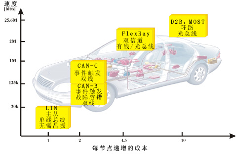
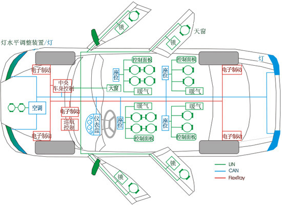
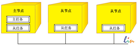
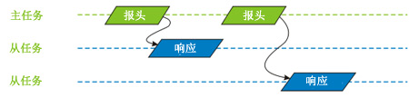
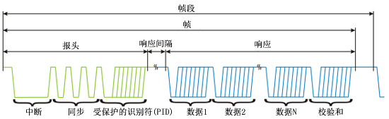
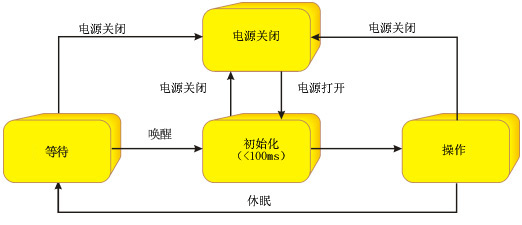
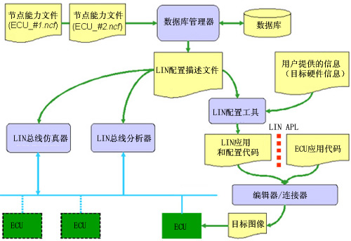
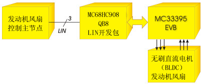
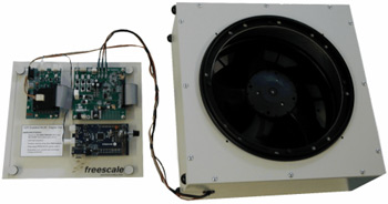
This article aims to introduce the low-cost serial communication protocol of the local Internet (LIN), which is mainly used in the concept of distributed electronic systems and network-based vehicles for automobiles. This article refers to the address: http:// This article introduces the current LIN version, which is the LIN 2.0 upgrade from the original LIN1.3 version, and introduces some basic knowledge of the LIN network. As an example of implementing LIN 2.0, this article also introduces the application of LIN's brushless DC motor (BLDC) engine fan control. It is based on Freescale's 8-bit MCU and uses the Volcano LIN development kit. In-vehicle network solution One of the many changes that new technologies bring to vehicles is the increasing number of electronic components. At the same time, advanced control systems with a variety of sensors, actuators, and electronic controllers have placed great demands on automotive communication technology. Obviously, these requirements can only be met by using this kind of network solution. Because the environment inside the car is different, this article will introduce three main communication standards that can meet the requirements of cost, security and communication speed. FlexRay CAN - Controller Area Network LIN - Local Internet The comparison of the above three communication standards in terms of communication speed and cost per node is shown in Figure 1. Figure 1: Major Automotive Communications Agreement Each communication standard has its own advantages and target application platform: FlexRay - high speed (up to 10 Mbps per channel), dual channel, time-triggered, powerful fault-tolerant protocol, designed for use as a backbone. The general target application is the so-called X-by-wire concept. Its purpose is to replace the traditional brake pedal and brake or the mechanical transmission between the steering wheel and the wheel by electronic signal transmission. CAN (Controller Area Network) - Medium speed (up to 1 Mbps), single channel, two-wire fault tolerant protocol, is currently widely used not only in the automotive industry, but also in many industrial applications. Target applications for the CAN protocol can include motor control, suspension control, and in-vehicle infotainment. LIN-Local Interconnect Network - Low speed (up to 20kbps), single-wire low-cost protocol for end-node applications. The concept of LIN is destined for use in sensors/actuators, typically for low-speed communications, where speed is not a critical factor. Figure 2 is an example of a bus-oriented automotive design concept. This design shows the coexistence of three communication protocols. Figure 2: Bus car concept LIN--Local Internet As mentioned above, LIN is a low cost single-wire serial communication interface. It is based on a universal UART/SCI interface and guarantees reliable data transfer at a baud rate of 20 kbps. The LIN bus is typically used in integrated devices such as doors, steering wheels, seats, temperature control, and engine cooling fans. Among these devices, the cost-sensitive nature of the LIN network has led to the adoption of a range of advanced mechatronic devices such as smart sensors/actuators. In addition, by replacing the analog code with digital coding, the mechatronics can be easily connected to the vehicle network system and easily diagnosed and repaired, including system reprogramming and updating. Another major feature of the LIN protocol is that synchronization can be done automatically from the node without the need for a crystal or ceramic oscillator. The simplicity of this feature and SCI-based communication is a major factor in the cost-effectiveness of any LIN implementation. Operational basis The operational concept of LIN is based on a master-slave topology. In this case, the LIN cluster (synonym for LIN network in LIN 2.0) contains one master node and several (up to 15) slave nodes. Figure 3: Operational concept As shown in Figure 3, the LIN node can actually be divided into two separate parts: Master task, responsible for deciding when to transmit which frame From the Slave task, provide data that will be transmitted over the LIN bus and allow the LIN cluster to be woken up from low power modes through the node. A typical primary node contains primary and secondary tasks, while a secondary node contains only secondary tasks. Frame composition The unit of data transmitted over the LIN bus is called a frame. Each frame contains two main parts: The header provided by the main task. The response from the task processing. Figure 4: Composition of the LIN frame The header contains the following sections: Break - The dominant state of the at least 13-bit long LIN bus, generated by the main task, containing each LIN frame. Synchronisation field - A bit field with a data value of 0x55 that enables the slave task to synchronize with the master clock. Protected Identifier (PID) - Uniquely defines the message content but does not define the recipient's address. The PID starts with a 6-bit identifier followed by two parity bits. The response part of the LIN frame is provided by the node from the task and can be divided into the following two parts: Data field - Transfers 1 to 8 bytes of data. Checksum field-- contains the sum of the 8 bytes of the reverse conversion, including the subsequent (Carry Over) data bytes. The structure of the LIN frame is shown in Figure 5. Figure 5: LIN frame structure There are three types of data content transmitted in the response portion of a LIN frame: Signal - The ladder value or array of bytes contained in the data field of the response. In this case, the ID of the frame must be between 0x00 and 0x3B. Note that the position of the signal in the data segment is fixed for frames with the same PID. Diagnostic information - used to transfer diagnostic or configuration data. This information is always 8 bits long with a reserved ID number. The 0x3C ID is used for the primary request and 0x3D is used for the secondary response. Reserved information - can be used for user-defined extensions (in this case ID equal to 0x3E) or reserved for future protocol improvements (ID set to 0x3F). The transmission of the main task to the header is based on the cluster's schedule. The schedule specifies the order in which frames are transmitted, as well as the interval between the current and next frames. Since the number of timetables is theoretically unlimited, several different timelines can be defined to meet the different needs of the cluster operation. The timeline concept is a mechanism that helps ensure that the network is not overloaded and that there is guaranteed data transfer. Network management Network management in LIN refers only to the cluster wake-up and go-to-sleep processes. All other network management functions, such as configuration detection or limp hom management, are done by the application. If you want all slave nodes to enter low power mode, the master will issue the first MasterRequest frame with zero data byte. This frame is a sleep command. The slave node software is responsible for handling all the steps required to properly enter the low power mode. In addition, if the LIN bus is inactive for more than 25,000 bits of time (more than 4 seconds with the LIN 2.0 specification), the slave node should also automatically enter the low power mode. In order to wake up a sleeping LIN cluster, any node can issue a wake-up command. The wake-up request is issued by forcing the bus into a dominant state of 250ms to 5ms. Each slave node can detect a wake-up request and is ready to receive bus commands within 100 ms. The LIN node power management state diagram is shown in Figure 6. Figure 6: LIN Node Power Management LIN evaluation In 1996, Volvo and Volcano Communications (VCT) developed a UART/SCI-based protocol for the Volvo S80 series, the Volcano Lite. This agreement is an integral part of the vehicle communication system. In 1997, Motorola partnered with Volvo and Volvo to help them improve the Volcano Lite protocol to meet a variety of needs (such as automatic synchronization of slaves without crystals) and to develop open standards that support a variety of semiconductor products. In December 1998, Audi, BMW, Daimler Chrysler and VW were also joined, resulting in the formation of the LIN Association (http://). The LIN 1.0 version was released in July 1999 and was heavily influenced by the VLIT bus used by some car companies. The LIN standard was updated twice in 2000 to produce the LIN 1.2 version. In November 2002, the LIN Association promulgated the LIN 1.3 standard, which mainly modified the physical layer and improved the compatibility between nodes. The current standard version, LIN 2.0, was released in September 2003. Since the LIN2.0 version is the current standard, this article mainly introduces this version. Since Audi, BMW, Daimler Chrysler, VW, Porsche and VCT have found some problems in the implementation process, a new version of LIN is currently being developed. In May 2005, VCT was acquired by Mentor Graphics (http://) as part of a larger company, enabling continuous support and development of VCT's complete product line. LIN 2.0 specification package The LIN specification version 2.0 reflects the development trend pointed out by the LIN Association. It also includes information provided by the SAE J2602 Task Force, especially in terms of the use of existing slave nodes. The LIN 2.0 specification package contains the following sections: The LIN physical layer specification describes the physical layer, including bit rate, clock tolrerance, and so on. The LIN protocol specification describes the data link layer of LIN. The LIN API specification describes the interface between the network and the application, including the configuration and diagnostic layers. The LIN Configuration Language Specification describes the syntax and semantics of the LIN documentation, which is used to configure the complete network and serve as input to development and analysis tools. The LIN Diagnostics and Configuration Specification describes services that can be deployed at the data link layer to provide information for diagnostic messages and node configuration. The LIN node functional language specification defines the format used to describe an existing slave node. These slave nodes can be used with Plug and Play tools to automatically create LIN description files. The LIN development workflow in Figure 7 shows how the various parts of the LIN 2.0 specification package form a whole. Figure 7: VCT LIN development workflow The LIN 2.0 and LIN 1.3 specification packages can be ordered free of charge after registration at http:// By comparing the LIN1.3 and LIN 2.0 specification packages, we can see that the two most important changes are standardized support for configuration and diagnostics, as well as the specified node capability files. Their goal is to simplify the use of existing nodes. Other important changes include: The LIN API (part of the LIN specification package) is required for all nodes programmed in C. An improved checksum has been added (the LIN2.0 checksum also includes the PID byte). Added node configuration commands. Standardized and mandatory LIN product identifiers (vendor ID/feature ID/version ID) are part of the configuration. Added diagnostic and diagnostic APIs. New frames and signal types are defined so that sporadic frame and byte array signals can be used. Added the required response error (Response_error) from status monitoring. Separate the sleep (goto_sleep) and wake (wake_up) signals. Automatic bit rate detection has been added to the specification. LIN 2.0 is an extension of LIN 1.3, so the LIN 2.0 master node can handle clusters containing LIN 1.3 and/or LIN 2.0 slave nodes. Naturally, some of the special features of LIN 2.0 (including enhanced checksums, reconfiguration, diagnostics, etc.) cannot be requested from a node in LIN 1.3. However, the LIN 2.0 slave node cannot be run with the LIN 1.3 master node (because the LIN 2.0 slave node needs to be configured). SAE J2602 LIN Working Group The goal of SAE J2602 is to improve interoperability and interoperability between different LIN devices in the network by meeting the vague, contradictory or optional requirements of LIN 2.0. The main differences between the provisions of J2602 and the LIN 2.0 specification include: The baud rate is fixed at 10.417 Kbps. Since the slope is optimized for a fixed baud rate, better EMC can be achieved. Communication between slave nodes is not recommended. Event-based messages are not allowed. All configuration and diagnostic services are optional except for Sleep and Targeted Reset. SAEJ2602 also addresses other requirements not found in LIN 2.0 (such as fault-tolerant operations, network topologies, and built-in standardized reports). In general, the design of SAEJ2606 takes into account the long-term goal of implementing custom slave nodes, while LIN 2.0 assumes the use of MCU-based implementations. Therefore, J2602 expects to further save costs by customizing slave nodes. Possible implementation on silicon components Several LIN driver implementation strategies are available depending on the capabilities provided by the target MCU. For MCUs without a UART module, a Bit-Bang solution is required to build the UART functionality into the software using a timer and two general-purpose IO pins. The main advantage is that an MCU without a UART is generally the cheapest processor. On the other hand, such CPUs are very sophisticated and require an interrupt request to be sent for each byte. Finally, this solution typically requires more memory than a UART-based solution. For example, such a LIN driver can be found in Freescale's 68HC908QY device. An MCU with a standard UART (SCI) module generally means that the software installation of the drive is simpler, but on the other hand, the UART module increases the MCU cost of the final solution. The advantage of this solution is that the CPU is less loaded than the Bit-Bang solution, because LIN-based interrupts are only performed for each byte received. The LIN optimized UART module's MCU is the next step in reducing the software portion of the driver and adding features/features. The enhanced SCI module used in Freescale's 68HC908EY or 68HC908GR devices provides baud rate adjustment and arbitration module options to measure input signals without the need for an additional timer (useful for LIN sync messages). On the other hand, this approach may increase the cost of the final design. Last but not least, the ideal solution should use a LIN-specific UART module. The SLIC (LIN Slave Interface Controller) module of Freescale MCUs (such as the 68HC908QL device) is an example. This solution is more cost and more complex than a standard UART solution and requires SLIC-optimized drivers. On the other hand, the SLIC provides the following functions: automatic synchronization, automatic baud rate adjustment, greatly reduced interrupts compared to any of the above solutions, automatic checksum generation and verification. Therefore, it allows the MCU to be dedicated to user applications. In addition, a very interesting solution is to move all LIN-related calculations to a coprocessor module that supports LIN. Freescale's MC9S12X series uses this approach. These products are equipped with a completely independent core X-gate RISC coprocessor that frees the entire LIN communication load from the CPU core, ensuring that the CPU is available for user applications at all times. LIN2.0 application examples As mentioned earlier, the LIN communication protocol is designed for automotive sensor and actuator applications. However, its use is not limited to these fields. The LIN-supported brushless DC motor (BLDC) engine fan control application described here is an example of LIN's application in other fields. Brushless DC motors (BLDC) are becoming more common in automotive applications and are used primarily in air conditioning control and engine cooling fans. Compared to brushed DC motors, brushless DC motors (BLDC) use electronic switching instead of mechanical switches, thus improving the reliability and efficiency of the entire system. Moreover, since the brushless DC motor (BLDC) rotor can generate rotor flux, higher electromechanical conversion efficiency can be achieved. Brushless DC Motor (BLDC) engine fan control applications that support LIN use the LIN2.0 communication protocol in closed-loop, PWM-enabled brushless DC motor (BLDC) applications. The brushless DC motor (BLDC) is driven by a Hall sensor for rotor position detection, and the application also incorporates current and overvoltage detection. The main part of this application is shown in Figure 8: Figure 8: Brushless DC Motor (BLDC) Engine Fan Control with LIN Support As shown, the brushless DC motor (BLDC) engine fan control hardware that supports LIN is very simple and consists of four parts: Engine Fan Controls LIN Master Node - Provides the required fan speed information for the LIN cluster, as well as run/stop commands and error tracking. MC68HC908QB8 LIN Development Kit - is a LIN slave node that handles brushless DC motor (BLDC) control functions and provides actual fan speed information and fan run/error status information for the cluster. The evaluation board's LIN Development Kit Series (EVB) is a way for developers to easily develop their respective LIN-based projects without having to focus on hardware development. These evaluation boards are currently available for Freescale Semiconductor's wide range of 8/16-bit MCUs: from the very small, inexpensive MC68HC908QY4 MCU to the powerful MC68HC908S12C32. In this application, we chose the MC68HC908QB8, which is a member of the low-cost, small 8-bit MCU family. MC33395 EVB - for power design. Freescale Semiconductor's evaluation board concept is not limited to this MCU-based board, but includes an evaluation board based on the Freescale SMARTMOS family. The MC33395 EVB is ideal for a wide range of 12V motor control applications, including zero-crossing and back EMF (BLDC) rotor position detection methods, making it easy to use advanced motor control programs. Brushless DC Motor (BLDC) Fans - This application uses the EBM-Papst W3G300-EQ22-90 axial fan. The following are the functions of the engine fan system. The master node sends information about the required brushless DC motor (BLDC) duty cycle, on/off command, and reset signal (to clear the overcurrent and overvoltage signals on the slave node). The required speed can be set directly on the motherboard or sent to the master via the advanced CAN bus. The node is provided with the actual brushless DC motor (BLDC) speed, current over-current and over-voltage flag. The first step in adding a LIN 2.0 link to a "standalone" engine fan is to create a cluster message policy. It fully describes the communication between different devices in the cluster. It includes a list of all frames with defined frame IDs, frame issuers and users, and data field content (including signal structures). It is also important to create a schedule for the cluster. These should be included in the LIN description file (*.ldf), and its structure is specified by the LIN specification package (LIN configuration language specification). For the software part of the project, Volcano (visit for more information) LIN Target Package (LTP) is used as a LIN 2.0 driver. This tool can generate LIN-specific C code files from cluster LDF files. These files are then added directly to the user compiler/linker to add a LIN linker to the project. As a result, application developers only need to write user-specific programs without having to spend time developing programs related to LIN communications. For more information on this, see the Freescale Semiconductor Application Note AN2767, "LIN 2.0 Links on Freescale 8/16-Bit MCUs Using Volcano LTP." It is a simple, easy-to-read article that describes and describes the implementation of LIN 2.0. Brushless DC Motor (BLDC) engine fan control supporting LIN is described in detail in the Freescale Semiconductor AN2983 Application Guide. This application guide includes the complete software code, which can be downloaded for free from the Freescale website. Figure 9 shows the real picture of the application. Figure 9: Actual installation of a fanless DC motor (BLDC) engine fan control that supports LIN Freescale Semiconductor offers a broad portfolio of LIN products, including 8/16/32-bit master MCUs and 8/16-bit slave MCUs. Moreover, the Analogue Product Group also offers a variety of products, including LIN physical layer interface, LIN/CAN SBC (system based chip) and IDC (Intelligent Distributed Control). IDC products are highly integrated single-packaged chips that include an 8-bit MCU, LIN physical layer interface, voltage regulator, and various power-driven (SMARTMOS) components such as half-bridge, high/low-side switches, Hall sensor inputs, and more. This solution is ideal for space-constrained applications such as rearview mirrors or window regulators.
The 6KV/6.6KV Medium Voltage Variable Frequency Drive is a product accumulated by FGI for over 20 years. The system adopts modular design, mainly including phase shift transformer cabinet, power unit cabinet and control cabinet, etc. The Mv Vfd has the advantages of low input harmonic content and high power factor. The High Voltage Drive is widely used in pumps, fans, woodworking machinery, cement production and other industries.
6Kv And 6.6Kv Medium Voltage Drives Mv Drives,Mv Vfd,High Power Motor Drives,6Kv And 6.6Kv Medium Voltage Drives,Medium Voltage Motor Starter,High Voltage Motor Controller SHENZHEN FGI SCIENCE AND TECHNOLOGY CO., LTD , https://www.fgi-tech.com