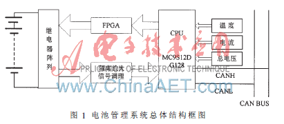
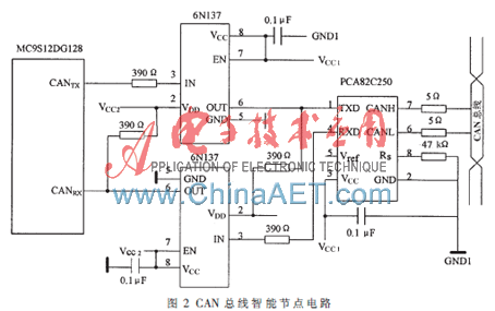
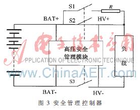
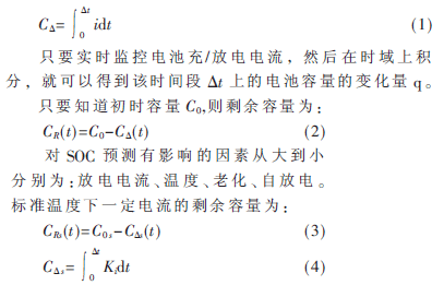
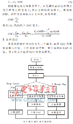
The safety, cost of use and cruising range of vehicle power batteries have always been the main factors affecting the promotion and application of electric vehicles. Based on the existing battery technology, an effective battery management system can protect the vehicle power battery, extend its service life, improve the cruising range and reduce its use cost. It is a very key technology to accelerate the development of electric vehicles. . The core state of charge (SOC) estimation of the battery management system is the most important [1]. In this paper, the field programmable gate array FPGA is used to improve the existing analog multi-way switch to collect battery information, improve the acquisition speed, and expand the number of batteries collected. This article refers to the address: http:// 1 Electric vehicle battery management system solution The power battery pack consists of 400 single-cell lithium-ion batteries with a nominal voltage of 3.2 V and a capacity of 11 A. The power battery pack consists of 4 and 100 strings. The voltage detection adopts the distributed detection method, which divides the battery into several groups, and uses multiple sets of detection circuits to detect each of the four parallel cells in a time-sharing manner. This detection technology is relatively intuitive. In order to detect the voltage of each battery, it is necessary to introduce the voltage signal of each battery into the detection device, and adopt multi-channel switching technology, that is, switch the voltage signals of the multi-cell cells to the same one through the switching device. Signal processing circuit. “Switching†dynamically changes the reference point to ensure that each measurement is the terminal voltage of a single cell; while the differential input ensures that the battery pack and the detection circuit are not shared, although not fully isolated, but Ground connection is safe [2]. Communication is carried out using the CAN bus. The design of the entire battery management system adopts a modular design idea. According to the function, it can be divided into two parts: the control circuit and the signal acquisition circuit, as shown in Figure 1. 1.1 control circuit design The control circuit comprehensively collects the voltage, current and temperature information, performs SOC estimation on the battery, and communicates with the host computer and the vehicle control system through the CAN bus interface. The MC9S12DG128 is a high-performance 16-bit microcontroller HC12 series with a central processing unit of 16 bit HCS12 CPU. It has 2-channel SPI, 2-channel SCI, an 8-channel 16-bit enhanced capture timer, an 8-channel 8-bit or 4-channel 16-bit PWM, two 8-channel 10-bit ADCs, two MSCAN modules and an I2C bus. In addition, the MC9S12DG128 also includes 29 independent digital I/O ports, of which 20 I/O ports have interrupt and wake-up functions. Therefore, using the MC9S12DG128 chip as the main controller can make full use of the advantages of rich on-chip resources, fast acquisition and processing of data, so that complex algorithms and accurate estimation of SOC can be realized, and the battery management system based on the traditional single-chip microcomputer is effectively limited. The algorithm is simple. 1.2 communication interface design In this system, the CAN bus intelligent node circuit is composed of MC9S12DG128 built-in module CAN control module, CAN bus driver PCA82C250 and high-speed optocoupler 6N137, which can realize data communication on CAN bus. Its design is shown in 2. As the interface between the CAN protocol controller and the physical bus, the PCA82C250 meets the design requirements of the high-speed communication rate of 1 Mb/s [3] in automobiles. It has the ability to provide differential transmission to the bus and differential transmission to the CAN controller, in accordance with ISO11898 [4]. The PCA82C250 is also resistant to transient disturbances in the automotive environment, protecting the bus, and its slope control reduces radio frequency interference (RFI). As a differential receiver, it is resistant to a wide range of common mode interference and electromagnetic interference (EMI). 1.3 Design of the equalization module When the electric vehicle battery pack is used in series by a plurality of single cells, even if the performance of the single-cell battery is excellent, the characteristics of the individual cells used in the group are inconsistent, which may cause over-charging and over-discharging of the individual cells in the battery pack. The situation is seriously inconsistent, which affects the quality of the entire battery pack [5]. To solve the above problem, a typical method is to use a heating resistor bypass shunt equalization method. That is, each unit battery is equipped with a discharge balance resistor. When a battery voltage is higher than other batteries exceeds the set value, the MCU-controlled multiplex switch is closed, and this section is shunted by the discharge balance resistor to lower the battery voltage. The cycle allows the battery cells of the battery pack to be charged in a balanced manner. 1.4 Design of the safety module The total voltage of the electric vehicle power battery pack is generally above 300 V, so the safety control module is indispensable [6]. The security manager shown in Figure 3 has four main parameters: BAT+, BAT-, HV+, and HV-. It manages three relays S1, S2, and S3, and R is a pre-charging resistor. This system mainly judges the battery safety by measuring the changes of the above four parameters, and manages by switching relays. The leakage current generated by the grounding resistance of the positive and negative busbars to the ground is used to measure the grounding resistance of the busbar to the ground, thereby determining the ground fault of the busbar. This technology does not need to superimpose any signal on the busbar, it will not have any adverse effect on the DC bus power supply, and can completely eradicate the misjudgment and missed judgment caused by the distributed capacitance of the busbar to the ground. 2 SOC prediction The battery state of charge SOC is an important parameter describing the state of the battery. The methods for performing SOC prediction mainly include open circuit voltage method, load voltage method, Ah method, and DC internal resistance method. If there is enough data, the battery model can also be built using adaptive control calculations [7]. The design is based on the Ah method, and the SOC is estimated by the load voltage method and the internal resistance method. The relationship between the charge and discharge capacity of the battery and the charge and discharge current i is: Where C0 s is the total amount of electricity discharged by the standard discharge current at the standard temperature; C? s is the amount of electricity actually used to discharge the standard discharge current at standard temperature; K = ωi × δi is the current correction coefficient, and ωi is the standard temperature Next, the ratio of the amount of electricity discharged by the standard current I discharge to the amount of electricity discharged by the discharge current of different discharge currents, δi represents the temperature correction coefficient. Due to the effect of battery aging on the remaining capacity, C0 s is not equal to the battery nominal capacity q, their relationship: The system collects the temperature and voltage according to the setting of the three flag bits, and the collected voltage data is communicated by the CAN bus. In this paper, a distributed battery management system is studied by using advanced technologies such as single chip microcomputer, FPGA and CAN bus, and functions such as data acquisition, SOC estimation and CAN communication are realized. The hardware and software of the battery management system were debugged on the codewarrior and quartus software. The system has high prediction accuracy and strong practicability, and is expected to be applied to the field of electric vehicles.
About PEW Enameled Copper
Wire.
According to design of motor, transformer and
high-speed winding machine, PEW product has the advantages of good paint film
continuity, good flexibility and adhesion. high surface strength. breakdown
voltage is increased by 60% compared with national standard. Suitable for
manual and automatic winding machine .
Oxygen free copper covered polyester painting, Inner packing PT25/60/90/200 Plastic Spool.Outer packing: Carton box + Mooden box.
Insulated Copper Wire,Pew Enameled Copper Wire,Polyester Enameled Copper Wires,Enameled Copper Magnetic Wire HENAN HUAYANG COPPER GROUP CO.,LTD , https://www.huaonwire.com