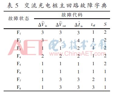
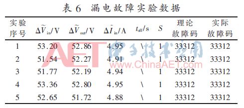
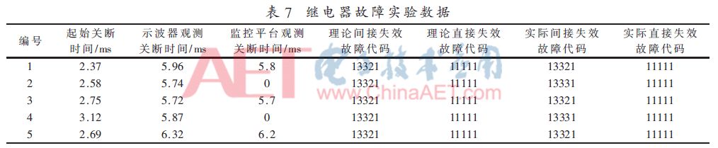
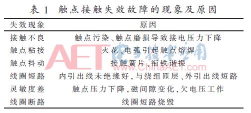
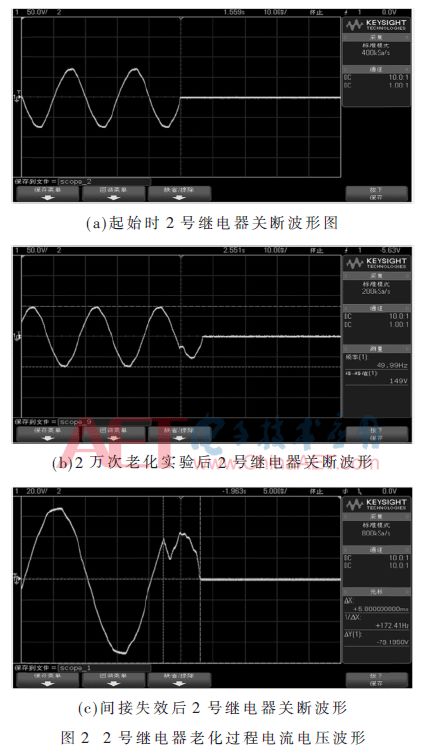
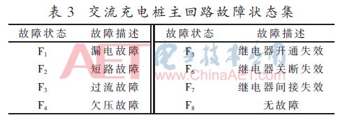
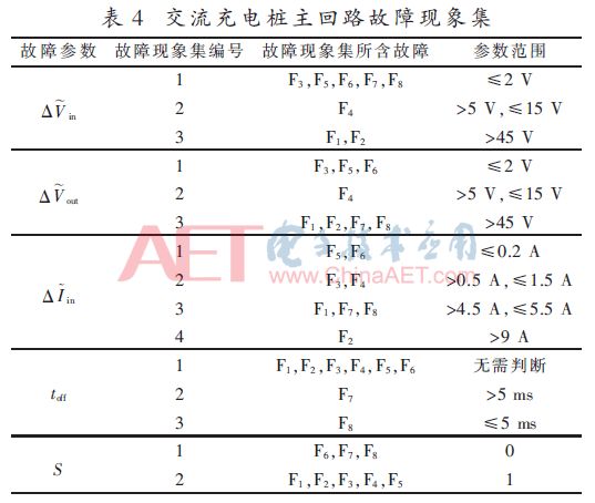
Summary: In order to detect and diagnose the possible faults of electric vehicle AC charging piles, combined with the characteristics of electrical components in the charging piles, the main fault types of the AC charging piles were analyzed, by extracting the relevant electrical characteristics of the main circuit in the AC charging piles, and using The fault dictionary method detects faults. Subsequently, an experimental platform was established to simulate the occurrence of various faults and verify the effectiveness of the fault dictionary method for fault detection of AC charging piles. The results show that the fault dictionary method has a good diagnostic ability for detecting typical faults that may occur in the AC charging pile. 0 Preface Nowadays, traditional fuel vehicles have many negative impacts on the world's energy and environment due to problems such as large oil consumption and serious exhaust emissions [1]. In this context, governments of various countries regard energy conservation and environmental protection as an important direction for the development of the automobile industry. Electric vehicles are powered by electric energy and driven by electric motors. The operation process is more environmentally friendly, so they are receiving more and more attention [2-3]. Charging equipment is a supporting facility for charging electric vehicles and an important part of the electric vehicle industry chain [4]. The AC charging pile is the most widely used charging equipment, ensuring the safe operation of the equipment, timely warning and detecting equipment failure, which are very worthy of discussion. 1 Failure mode analysis of AC charging pile The AC charging pile is a special device that provides a man-machine interactive operation interface and an AC charging interface for an electric vehicle with an on-board charger, and has a measurement, control and protection function [5]. The main circuit of the AC charging pile is directly affected by the current and voltage stress. Become a high incidence of faults in AC charging piles. The main circuit usually includes a circuit breaker, a relay, a charging interface, an energy meter, and a cable. Combined with the specific characteristics of these power components and charging pile charging, the circuit faults of the AC charging pile are usually divided into two categories: soft faults and hard faults. [6]. Hard faults refer to some large and variable faults, such as short circuits, open circuits, and component damage. These faults can cause the entire circuit to fail, and even cause the original system to be destroyed [7]. Soft faults are usually called gradual faults, which are mainly caused by the long-term aging of components and components causing their parameters to exceed the tolerance range. Under normal circumstances, the system can continue to operate after a soft fault, but the work efficiency is greatly affected. In the long run, the system will cause more serious faults [8]. 1.1 Hard failure mode analysis Electric leakage and short circuit are both types of hard faults that are prone to occur in the main circuit of the AC charging pile. Once a leakage or short circuit fault occurs, the AC charging pile will not work properly. The characteristic curve of voltage and current in the main loop when leakage fault and short-circuit fault occur is shown in Figure 1, where curve 1 is the voltage curve and curve 2 is the current curve. In actual situations, due to the presence of leakage protectors and circuit breakers in the main circuit of the AC charging pile, the final voltage and current of the main circuit will drop to 0 no matter whether a short-circuit fault or a leakage fault occurs. The difference is that because the operating current of the leakage protection is very small, usually within tens of milliamperes, the voltage and current curve of the main circuit is relatively stable when a leakage fault occurs, and it will not change drastically; and the short-circuit protection action time is close to the magnitude of the short-circuit current Relatedly, when the short-circuit fault occurs, the current of the main circuit will increase sharply first, and then the circuit breaker will act to cut off the main circuit. At this time, the voltage and current of the main circuit will quickly drop to 0. Therefore, compared with leakage faults, short-circuit faults have a greater rate of change of current in the main circuit. 1.2 Analysis of soft failure modes Soft faults in AC charging piles are common in switching devices such as electromagnetic relays. The electromagnetic relay will be affected by a variety of stresses such as heat, vibration, and chemistry during its life cycle. The internal components will be aged to a certain extent, and the performance of the relay will gradually degrade until it fails [9]. The failure rate of relay contacts is the highest, and contact failure is the most important cause of relay failure [10]. Common contact failure phenomena and causes are shown in Table 1. Analyze Table 1, and divide the contact faults of the relay contacts into two categories. The first category includes contact bonding, coil short circuit, and coil disconnection, which can prevent the relay from turning on and off normally. However, these types of faults are usually sporadic, and the probability of faults will gradually increase with the aging process. Therefore, these types of faults are still classified as soft faults, and they are called direct relay failures. The second category includes poor contact, contact jitter, and poor sensitivity. This type of failure reduces the relay's on-off performance, which is called an indirect failure failure [11]. 1.2.1 Direct failure analysis There are two cases of relay failure failure, turn-on failure and turn-off failure. When the relay control signal is inconsistent with the actual on-off status of the relay, that is, the relay fails to open correctly, it has a direct failure fault, which is also the basis for judging the direct failure failure of the relay. 1.2.2 Indirect failure analysis Relay indirect failure fault usually affects the turn-on or turn-off time of the relay, and the relay turn-on or turn-off time exceeds the tolerance range as a single indirect failure. Take the cumulative 6 indirect failure faults or two consecutive indirect failure faults as the criterion of indirect failure faults. Ten qualified products are randomly selected and numbered in a certain type of relay, and the relay aging experiment is carried out at the rated current. A 350 MHz oscilloscope is used to observe the input and output voltage of the relay and the current waveform flowing through the relay. When the read current and voltage waveform data meet the indirect failure fault criterion, record the time when the relay is switched on and off. The experimental results are shown in Table 2. It can be seen from Table 2 that during the aging process of the relay, the off-time will increase significantly, while the pull-in time will not change much. Take relay No. 2 as an example, observe the turn-off waveform during relay aging through an oscilloscope, as shown in Figure 2, and analyze the characteristics of the relay turn-off waveform. At the beginning of the experiment, the charging waveform was ideal and the relay performance was good. When the relay is turned on and off 20,000 times, the relay turn-off waveform jitter increases and the turn-off time becomes longer. When the experiment was conducted to more than 30,000 times, the relay failed indirectly, the jitter of the relay off waveform was further intensified, and the off time also increased. After that, the aging test was continued, and the relay failed directly after 5 minutes. Normally, as the number of switches increases, the performance of the relay will continue to deteriorate, and indirect failure faults and direct failure faults will appear one after another. In summary, if the relay status information, relay input and output voltage, current flow, and relay operating time are used as fault parameters, by comparing the changes of each characteristic parameter, you can determine what kind of fault occurred in the relay. At the same time, because the failure of the relay is a gradual failure, the detection of the off-time of the relay can also be used for early warning of the failure of the relay. 2 Fault dictionary Fault dictionary method is a fault diagnosis method based on qualitative experience [12]. By extracting circuit characteristic quantities (such as voltage, current, amplitude-frequency characteristics, etc.) under different fault conditions, and sorting the extracted data into a dictionary corresponding to the fault, once the circuit device fails, the actual measured data and The data stored in the fault dictionary is compared to quickly find the location of the fault and the corresponding components. To build a fault dictionary, we must first determine the set of fault states, that is, to clarify the abnormal state or fault type that may occur in the AC charging pile. Through the analysis in the previous section, the common faults of AC charging piles mainly include leakage, short circuit, overcurrent, undervoltage, direct relay failure and indirect relay failure, as shown in Table 3. Then divide the fault phenomenon set, and clarify all the fault types included in each fault phenomenon according to the relevant theory or experiment. The division process takes the relay input and output nodes in the main loop as the test nodes and selects the absolute value of the change in the relay input and output voltage and current effective value, circuit state switching time and relay status information as the failure parameters, as shown in Table 4. Table 4 Finally, the fault codes of all fault types are summarized to form a fault dictionary, as shown in Table 5. It can be known from Table 5 that the fault codes of different types of faults in the fault dictionary are unique. As long as the fault code is determined, the corresponding unique fault type can be determined. 3 Experimental verification In order to verify the effectiveness of the fault dictionary for AC charging pile fault detection, an experimental platform was designed to simulate the working state of the AC charging pile main circuit, and a data acquisition module composed of current and voltage sensors and a single chip was used to simulate the current of the main circuit and the input and output voltage of the relay respectively Real-time collection is performed, and the collected data is wirelessly transmitted to the host computer. During the experiment, input an alternating current with an effective value of 50 V as the excitation signal, and connect four high-power ripple resistors of 40 Ω and 500 W in parallel as the load. Set the A / D sampling frequency in the MCU to 5 kHz, then the MCU collects 100 data in one cycle, the voltage signal sampling range is AC effective value 0 ~ 100 V, and the current signal sampling range is AC effective value 0 ~ 10 A. Simulate leakage fault and relay fault on the experimental platform. 3.1 Leakage fault verification Use the leakage test switch that comes with the circuit breaker to verify the leakage of the main circuit. The experimental data is shown in Table 6. It can be known from Table 6 that the established fault dictionary has a better ability to identify leakage faults. 3.2 Relay failure verification Re-select 5 good products in a certain type of relay and number them. Firstly, perform the aging test on the relay. When the relay has a single indirect failure, stop the aging test, turn on the relay for 10 min, then disconnect once and repeat this process This simulates the actual charging process of the charging pile. Continuously observe the off-time of the relay with an oscilloscope and collect the off-time of the relay. When the criterion of indirect failure is met, the failure code of the indirect failure is verified through the remote monitoring platform. Then continue the relay aging test until the relay fails to bond. When the relay fails to bond, the simulation charging experiment is conducted again, and the failure code of the bond failure is verified through the remote monitoring platform. The relay aging experiment data is shown in Table 7. It can be known from Table 7 that by reading the relevant feature quantities in the oscilloscope, the faults of the relay can be diagnosed correctly and effectively, which proves the effectiveness of the established fault dictionary for fault diagnosis of relays in AC charging piles. The data collected on the experimental platform has a good diagnostic accuracy for the hard faults of the AC charging pile and the direct failure of the relay in the AC charging pile, but there is a misdiagnosis for the indirect failure of the AC charging pile relay, which is due to the wireless There is a delay of up to several hundred milliseconds in the transmission process, and the data collection of the single-chip module on each sensor is not continuous. 4 Conclusion This paper analyzes the main fault modes and causes of faults in AC charging piles, and detects faults by extracting relevant electrical characteristic quantities and establishing fault dictionaries. Experiments have proved that the use of fault dictionaries can detect a variety of soft and hard faults in AC charging piles with high detection accuracy, which verifies the feasibility and effectiveness of fault dictionary method in fault detection of AC charging piles. It is of great practical significance for the actual troubleshooting of charging piles.
Features
A push button switch is a switch that has a knob that you push to open or close the contacts. In some pushbutton switches, you push the switch once to open the contacts and then push again to close the contacts. In other words, each time you push the switch, the contacts alternate between opened and closed. These types are commonly called latching switches. There are also Non latching push button switches that only maintain the switch contacts when the switch is help in position. Once the switch is let go, the current is broken and the switch turns off. Push switches are usually a simple on-off switch.
Push Switch,Push Button Switch,Micro Push Button Switch,Waterproof Push Button Switch Ningbo Jialin Electronics Co.,Ltd , https://www.donghai-switch.com

 Off is the off time of the relay when a fault occurs. The S parameter state 0/1 indicates that the relay should be in the off / on state. The parameter ranges are all empirical values ​​selected in the case of a sinusoidal AC signal with a main circuit input amplitude of 50 V and a frequency of 50 Hz, and a load of 10 Ω high-power resistors.