Application of CAN bus in locomotive monitoring system Taking Philips' SJA1000 as an example, the characteristics of CAN field bus, the function and structure of the controller and the basic content of CAN 2.0B bus protocol are introduced, and a train locomotive monitoring system based on CAN bus and its system performance requirements are described. System hardware construction, software design ideas and application results, which illustrate the advantages of CAN bus and a general design process for industrial field control systems.
We will do the High temperature resistance testing and 10
hours ageing treatment before the product out off the factory, which can
ensure the stability of each product.
Our LED products have 5 year warranty.
We are the best supplier for your light-emitting diode.
We supply variety of 850nm IR LED(Infrared LED) products. Including Through-hole 850nm LED, SMD 850nm LED and high-power 850nm LED. We can also produce 850nm LED according to your requirement.
For the Through-hole Light Emitting Diode 850nm LED,
850nm led is a infrared LED( IR LED ). Common infrared LEDs are like: 840nm IR LED, 845nm IR LED, 850Nm IR LED, 855nm IR LED and so on.
850nm LED 850nm LED,850nm IR LED,850Nm IR LED,5Mm 850Nm IR LED Shenzhen Best LED Opto-electronic Co.,Ltd , https://www.bestsmd.com
Keywords: CAN, fieldbus, SJA1000 initialization, locomotive monitoring system, signal detection, local area network
1 Introduction For the train locomotive monitoring system, the speed, accuracy, reliability, and flexibility of data measurement / transmission are all crucial. The previous locomotive data monitoring only provided the display and alarm of on-site data, and the addition of intelligent instruments on each device was relatively scattered. It was inconvenient to observe the locomotive operation status and carry out timely maintenance. The locomotive operation data could not be saved, and these data are to identify the locomotive Reasons for failure and important basis for maintenance; various operations of smart meters, such as zero adjustment, limits, and accuracy are affected by environmental and human factors, which affect the display and alarm functions of simple meters, and the harsh environment of the work site (high temperature, vibration, Electromagnetic radiation, etc.), resulting in poor real-time performance and accuracy. With the development of domestic fieldbus technology, it is necessary to update the original detection system in time.
The locomotive monitoring system itself has dozens of data acquisition nodes (using a single-chip microcomputer AT89C51), and a host industrial computer is responsible for data storage and recording. Due to the many acquisition points and the high acquisition frequency (20Hz), the data on the bus is usually compared Crowded, and the system has particularly high requirements for the accuracy of data transmission and the real-time nature of alarm data. In view of this, we chose CAN fieldbus to build a data platform, which combines flexibility, real-time, accuracy and reliability Advantage.
CAN is the abbreviation of Controller Area Net. It is a serial communication protocol developed by German Mercedes-Benz Motor Company in the 1980s. It is mainly used for data communication between multiple control devices and multiple instruments in automobiles. The road layer uses CAN2.0B protocol. Now, it has been widely used in various industrial sites, especially suitable for optimization, analysis and maintenance systems. In the 1990s, China began to study the application of CAN bus. At present, CAN bus technology has been applied in many fields.
This system is a local area network constructed in accordance with CAN2.0B. The bus controller adopts SJA1000 of Philips of Germany. The driver is PCA82C250 matched with it. The lower computer and the upper computer communicate bidirectionally via CANH and CANL twisted pair. The entire hardware structure of this system can be used as a standard node of the CAN network to form a tree-like network. It is the minimum composition and typical application of the CAN bus system.
2 CAN bus characteristics Introduction The biggest feature of the CAN bus is that each node in the network works in a multi-master mode. Each node can send information to other nodes point-to-point and point-to-multipoint at any time, regardless of master and slave, and has good flexibility.
Data transmitted simultaneously on the CAN bus uses non-destructive arbitration, priority transmission with a small ID, and delayed transmission of low-priority data. This is very effective for solving network paralysis, network congestion, and improving efficiency for a heavily loaded network.
CAN also has a strong verification function, and the error data is automatically retransmitted with high reliability.
In addition, the CAN communication medium selects twisted pair, the locomotive site space is narrow, and the field wiring, installation and disassembly of the twisted pair are relatively simple. The maximum communication distance is up to 10km, the bit rate can reach 1Mbps (the bit rate will be reduced when the communication distance is large), and 16 messages can be transmitted simultaneously. The operating temperature range of Philips SJA1000: -40 ℃ ~ + 125 ℃, storage temperature range: ï¼65 ℃ ~ + 150 ℃.
For the SJA1000CAN controller selected by the system, the main functional modules are: Interface Management Logic (Interface ManagementLogic), Receive FIFO Stack (Receive FIFO), Receive Filter (Acceptance Filter), Transmit Buffer (Transmit Buffer), and CAN Core Module ( CAN Core Block), the structure is shown in Figure 1 (see the information of Philips Semiconductors: ApplicaTIonNote-SJA1000 Stand-alone CAN Controller AN97076, 1997). 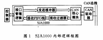
The acceptance filter receives the data converted by the CAN core module, and performs filtering processing through the register acceptance code register (ACR) and acceptance mask register (AMR). Only the data that meets the ID requirements are received. ACR provides local ID, AMR provides effective bit information when ID filtering. The receive FIFO stack is used to temporarily store the data received through the filter.
The send buffer (TB) stores the data to be sent, and the CAN core module reads from the send buffer and sends the data according to the CAN 2.0B protocol.
3 System functions and hardware implementation In addition to the functions provided by the conventional system, this system also has functions such as adjustable module priority (adjustable ID), adjustable alarm limit, and preservation of alarm history data.
The work site is composed of multiple analog instruments and some switching signals. Each instrument is equipped with a data acquisition board. The acquisition of the switching value is completed by a separate module similar to the analog quantity acquisition board. The lower computer adopts AT89C51 microcomputer of ATMEL company, mainly for communication data collection, simple judgment and data transmission preparation; the communication part is composed of bus controller SJA1000 and its matching driver PCA82C250, they can complete the data link layer and physical All the work of the layer; there is also a high-level industrial computer with 5M bytes of flash E2PROM, which can provide 100,000 erasures and a 10-year data retention period to store data before and after the alarm of each acquisition module. After the end of each operating cycle, the data in the E2PROM is exported for future performance analysis; the monitoring and alarm module is used to display and alarm the data in real time. In order to prevent the bottleneck phenomenon of the host computer, the alarm tasks of each module are scattered To complete to the lower computer, send the data to the upper computer only need to reset the position of the alarm flag; the bus terminal is connected to 100Ω ~ 120Ω resistor to suppress signal reflection and ensure communication reliability. The twisted pair connects each module node to form a multi-master control local area network. In addition, in order to prevent the system from running unexpectedly, X25045 (a peripheral device of the American Xicor company, which integrates three functions of Watchdog, reset controller, and CMOS serial E2PROM array with Block lock) is added as a watchdog, 4KB SPI ( Serial Peripheral Interface) E2PROM can store some important data such as the alarm limit of this node. The system topology is shown in Figure 2. 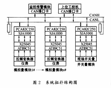
Each AT89C51 microcontroller actively sends data to the upper computer every 0.05s. The CPU of the lower computer is not too busy with the upper computer. Therefore, in order to prevent external interference signals from causing false alarms, the lower computer performs digital filtering on the data before sending data. : 0.05s is divided into 5 acquisitions, and the average value is sent to avoid false alarms of instantaneous high-frequency interference signals.
The data sent by the upper computer to the lower computer is generally directed to a certain lower computer, and the lower microcontroller receives the data by external interrupt INT0. The host computer monitors all the lower-level single-chip computers at all times, and the lower-level computer also monitors the upper-level computer from time to time and receives commands sent to itself.
When the SJA1000 receives data in the BasicCAN working mode, it is first loaded into the filter in the following order: ![]()
Among them, after the AMR code of the upper eight bits of the ID is masked, it is compared with the ACR eight bit reception code. If it matches, it is passed to the reception FIFO, otherwise it will not be received. Because the smaller the ID in the CAN2.0B protocol, the higher the priority. Therefore, the highest bit ID10 of the ID can be set as the flag of the alarm data (this bit is zero when the data exceeds the limit) to ensure the priority transmission of the module data with alarm. For the upper computer, to receive all the data of the lower single-chip microcomputer, the upper eight bits of the ID should be shielded, and the lower three bits ID2 ~ ID0 are used as the upper industrial computer to send commands to the lower microcontroller (such as modifying the alarm limit, etc.) The flag bit, therefore, the limit value of each module can be adjusted by the host computer sending commands during system operation.
When sending data, the lower computer first reads the limit value from the register to determine whether it exceeds the limit. If the limit is exceeded, ID10 is set to 0, otherwise it is set to 1. Then fill in the ID number of this module in ID9 ~ ID3, the command position will be sent, and then the microcontroller will not participate in the data transmission process, and other work will be completed by SJA1000 and PCA82C250. Since the ID can also determine the data priority, the MCU always reads the external 8-bit toggle switch from the P2 port as the ID first, so that the priority of each module can be artificially changed, which enhances the flexibility of the system.
AT89C51 sends data to the host computer in the main program, receives commands from the host computer in the 0 # external interrupt program, and uses the lower three bits of the ID to determine the meaning of the agreed command. Initialization program flow, where, at the beginning of each main program, in order to prevent the network from being uneven due to the reset time, acquisition cycle, and software of all the lower computers, the load on the BUS is uneven, and the workload of the upper computer is sometimes a big problem. The main program deliberately arranges different time delays for each reset, so that the moments when each module sends data can be evenly distributed. 

After the host computer receives the data, first check the alarm flag to determine whether it is an alarm. If so, write the first minute of data in the register and the corresponding time to the E2PROM, and continue to write the received alarm real-time data until the alarm One minute after stopping. Otherwise, the data plus the current time is stored in a register in a queue, the register is full, and the oldest data is flushed.
The monitoring and alarm module receives data like the upper industrial computer, except that each instrument module corresponds to an alarm device. N alarm devices display the overrun status of each instrument in real time, and another LCD screen displays real-time data of the alarm module without alarm. The real-time data of the module with the smallest ID is displayed.
The above describes the basic process and principle of communication between a separate lower-level acquisition module and the upper computer. The entire system consists of several relatively independent and similar lower-level modules and an upper computer. There is no communication between the lower-level computers temporarily.
5 Conclusion This system was developed for a Xi'an company to improve the locomotive console. After testing and software debugging until the commissioning operation (20 acquisition modules), the performance is stable, the fluctuation range of the collected data is less than 0.05%, and the data transmission during the commissioning The rate is set to 125kbps, no data loss, no data transmission error between the upper computer and the lower computer, the highest bit rate can reach 1Mb / s, anti-interference ability, high temperature resistance (-40 ℃ ~ +120 ℃), data accuracy Satisfactory, fully reflects the superiority of CAN bus. Unfortunately, after the locomotive instrument alarms, the problem can only be solved manually.
The next step will also consider the communication between the higher-level host computer and the sub-system (CAN field bus will still be used). If it can be achieved, the station and related departments will communicate with the trains, and the timely reporting and monitoring of the operation status and other issues. Will be solved.
2 Wu Kuanming. Practical Manual of Peripheral Devices of Single Chip Microcomputer-Volume of Data Transmission Interface Devices. Beijing: Beijing University of Aeronautics and Astronautics Press, 1998
3 Wu Kuanming. CAN bus principle and application system design. Beijing: Beijing University of Aeronautics and Astronautics Press, 1996
We are 850nm LED manufacturer from China.
When the 850nm led do not work:

When the 850nm led working:

We can customize the shape, the lighting angle, the number of emitting source, the flat pin LED and braided LED. Such as: infrared 5mm 850nm LED with 5 degree, infrared 5mm 850nm LED with 20 degree, infrared 5mm 850nm LED with 30 degree, infrared 5mm 850nm LED with 45 degree, infrared 5mm 850nm LED with 60 degree, infrared 5mm 850nm with 90 degree, infrared 5mm 850nm LED with 120 degree. Infrared 3mm 850nm LED with 3 degree, infrared 3mm 850nm LED with 20 degree, infrared 3mm 850nm LED with 30 degree, infrared 3mm 850nm LED with 45 degree, infrared 3mm 850nm LED with 60 degree, infrared 3mm 850nm with 90 degree, infrared 3mm 850nm LED with 120 degree ect.
There are many other shapes or color of lens for your choose. Customized infrared LED are available
For the SMD LED 850nm LED,
We can supply dual-chip infrared LED, three-chip infrared LED, multi-chip infrared LED, high voltage LED, flashing infrared LED and variety of size SMD LED. For instance: 3528 SMD infrared 850nm LED, 2835 SMD infrared 850nm LED, 3014 SMD infrared 850nm LED, 1206 SMD infrared 850nm LED, 3020 SMD infrared 850nm LED.
There are also have many other shapes to choose, like the 5050 SMD infrared LED, the 5730 SMD infrared LED ect. You can choose any one of them for your requirement.

Application of CAN bus in locomotive monitoring system
references
1 He Limin. SCM application technology selection. Beijing: Beijing University of Aeronautics and Astronautics Press, 1999