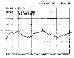
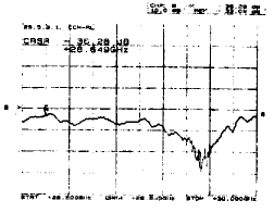
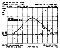
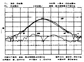
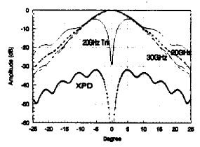
A broadband 20 / 30GHz ripple feed This paper introduces the 20 / 30GHz corrugated cone feed for tracking the data relay satellite system (TDRSS) ground measurement and control antenna, and gives the design performance and test results of the test piece. Radiation pattern equalization <1dB, cross-polarization is better than -26dB; at 18.1 ~ 20.2GHz, VSWR <1.12, at 28.5 ~ 30GHz, VSWR <1.05. 1. 20 / 30GHz ripple feed design For the lower frequency bands such as L, S, C, X, Ku, etc., the design and manufacturing method of ripple feed has mature technology, and as the primary feed of the TDRSS system Ka-band measurement and control antenna [1], its design It remains to be researched and explored with process manufacturing methods. On the one hand, due to the high operating frequency, the structure size of the corrugated trough of the corrugated horn and its input mode conversion transition section is very small (0.1 ~ 2mm); , Bringing greater difficulty to mechanical processing, the main difficulty lies in the precision-preserving processing method of the ring loading transition section, so it is necessary to adopt high-precision process manufacturing technology or new design methods. Figure 1 20 / 30GHz ripple feed structure 2. Ka-band feed design performance and measurement results The design result of the radiation characteristics of the corrugated feed HE11 mode is shown in Figure 2, and the calculation formula is [4, 5]: Figure 2 Calculated radiation pattern of ripple feed Among them: Q ± = ∫10J0 (xat) J0 (ut) S = ∫10J0 (xat) exp (-jφmt2) tdt The calculation pattern of HE21 mode is also shown in Fig. 2 [5]. The designed VSWR of the corrugated horn HE11 mode is less than 1.06 in the 18.1 ~ 20.2GHz frequency band; less than 1.02 in 28.5 ~ 30GHz. In the formula, xa0 is the eigenvalue of the TE11 module, and xa is the eigenvalue of the HEmn module. The measured HE11 mode performance of the 20-30GHz corrugated feed test piece is shown in Figure 3. The performance of the HE21 tracking module will be published in another article after the test is completed. Figure 3 (a) Figure 3 (b) Figure 3 (c) Figure 3 (d) Figure 3 Measured 20-30GHz ripple feed performance 3. Conclusion The ripple feed is one of the core components of the high-performance Ka-band TDRSS measurement and control antenna. This article introduces the design method and calculation results, and shows the measured test piece performance. The performance meets the requirements of the antenna system and achieves the intended development purpose.
Industrial Drone difference as the entertrainment drones, It is for some application purpose. Such as Security Patrol Drone, Inspection Drone ,Fire Extingurisher Drone ,Heavy payload Logistics Drone etc. Because these drones has different applications so they have different Drone Frame ,propulsion system, Drone Flight Controller and equipments. Usual long flight time, long distance control range request. Configration of Ground Control Station, Videolink Datalink, Zoom Camera , Gimbals etc.
Industrial Drone Security Patrol Drone, Inspection Drone,Fire Extingurisher Drone ,Heavy payload Logistics Drone shenzhen GC Electronics Co.,Ltd. , https://www.jmrdrone.com
Keywords: TDRSS Ka-band ripple feed
One method is to use other forms of feeds without corrugated horns, and the other method is to adopt a single-band design with a transition section as a variable-groove corrugated feed. Due to the operating frequency bandwidth (1: 1.65), both methods have a greater impact on the overall performance of the antenna system. In the literature [2], the corrugated horn with a variable groove deep transition is -10dB and -27dB at 20GHz and 30GHz respectively, which is very different. If it is used as a feed, the performance of the antenna system at 20GHz and 30GHz is very different. Especially 20GHz side lobes are difficult to meet the mandatory envelope requirement of (29-25lgθ) dBi. Other forms of feed have similar situations as well as equalization and cross-polarization of the pattern. After the demonstration of the plan, we adopted the ring-loaded widening band technology. When designing the transition section of the corrugated horn input mode, the first few corrugated teeth were intentionally widened to reduce the processing difficulty.We used a single corrugated sheet for precision processing Then the twenty corrugated sheets are fixed by high-precision tooling. In the final electroforming process, the actual processing accuracy achieved has passed the electrical performance test. The measurement performance of this corrugated feed completely meets the requirements of the antenna system, which also shows The design method and manufacturing process are very successful and effective.
The external dimensions of the designed corrugated horn are: mouth radius a = 59mm, phase center d = 177.5mm, horn half opening angle α = 12.56 °, length L = 264.96mm. Considering the TE21 mode tracking, the input end diameter is 17.8mm, the corrugated groove depth is 3 ~ 4mm, the minimum loading width is 0.1mm, w = 2mm, P = 3mm, the ring loading thickness is 0.3 times the corresponding corrugated groove depth, design method References [3] ~ [5]. The ripple feed structure is shown in Figure 1. The radius a of the transition section of the corrugated mode conversion adopts the {Aexp (Bx2) -A + a0} curve form in order to achieve broadband matching. 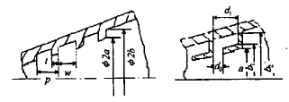

μ11j2 (xat) J2 (ut) exp (-jφmt2) tdt
![]()


