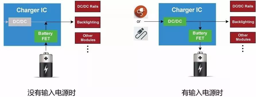
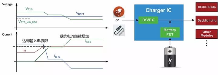
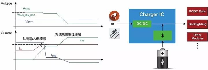
Today, MPS Xiaobian is here to discuss an important feature in charging ICs: dynamic path management. This strategy plays a crucial role in optimizing power delivery and ensuring system stability during the charging process. Dynamic path management dynamically adjusts the charging current based on the input power supply’s capabilities and the system’s load requirements. This ensures that the device charges as quickly as possible while maintaining stable power for the system. It also allows the system to start up immediately when power is connected, even if the battery is deeply discharged. In portable devices, the charging IC is a key component responsible for managing power flow between the input source, the battery, and the system load. Depending on the situation, the system can be powered by the battery, the input source, or both. To manage this efficiently, the charging IC must have advanced power management features, such as dynamic path control, to choose the optimal power source in real time. One common implementation of dynamic path management is Narrow Voltage DC (NVDC) mode. As shown in Figure 1, the system load is connected directly to the system bus (VSYS). The battery can power the system through a Battery FET, or the input power can supply it via a front-end DC/DC converter. Figure 1 When no input power is connected, the Battery FET is fully turned on, allowing the battery to directly power the system. Once input power is connected, the system bus voltage is regulated by the DC/DC converter, and the battery is charged through the Battery FET. However, the system load always has priority. The charging IC first supplies power to the system based on the available input power, and any remaining power is used for battery charging. Figure 2 During the charging process, if the total system load demand exceeds the input power capacity, the system bus voltage may drop. In response, the charging IC reduces the charging current to prevent further voltage sag, keeping the system running smoothly. If the input power still cannot meet the system’s needs after the charging current is reduced to zero, the system voltage will continue to fall until it drops below the battery voltage. At this point, the battery begins to supply power to the system through the Battery FET, entering what is known as the battery replenishment mode. Both the input power and the battery now provide power to the system simultaneously, ensuring uninterrupted operation. Figure 3 When the battery is over-discharged and input power is connected, the charging IC adjusts the system bus voltage to a minimum acceptable level. If the system voltage drops below a certain threshold, the charging current decreases. Additionally, if the battery is reverse-discharged, the IC controls the Battery FET to operate in the saturation region, preventing large inrush currents from damaging the battery. This smooth transition into and out of battery power is often referred to as the ideal diode mode for FETs. Figure 4 In the ideal diode mode, the Battery FET behaves similarly to a diode, operating in the saturation region. When input power is present and the system voltage is slightly lower than the battery voltage (e.g., 40mV), the charging IC adjusts the gate voltage of the Battery FET to maintain a specific voltage difference (e.g., 20mV, similar to an ideal diode’s forward voltage drop). As the discharge current increases, the gate voltage rises, reducing the FET's impedance and keeping the voltage difference at the desired level. Conversely, when the discharge current decreases, the gate voltage lowers, increasing the impedance to maintain the same voltage difference. In summary, dynamic path management is a complex but highly beneficial technique. It offers several advantages: First, it allows the system to power up instantly when input power is connected, regardless of the battery’s state. Second, it enables flexible adjustment of the charging current, prioritizing the system’s power needs. These features make dynamic path management essential in modern portable electronics, where efficiency and reliability are critical. Ethylene-Propylene-Diene Monomer EPDM Rubber Cold Shrink Tube is a kind of equipment used on power and communication cables indoor, outdoor, overhead, in water or buried. Ethylene-Propylene-DieneMonomer,EPDM cold shrink tube,Cold Shrink Tube,Cold Shrinkable tubing,Cold-shrink tube,EPDM Mianyang Dongyao New Material Co. , https://www.mydyxc.com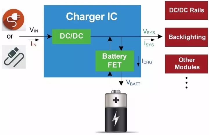
EPDM rubber is a terpolymer of ethylene, propylene and non-conjugated diolefin.EPDM rubber has excellent mechanical properties, puncture resistance and high tear resistance, weather resistance, ultraviolet resistance, ozone aging resistance, acid and alkali resistance, salt spray corrosion resistance, resistance to high and low temperatures of up to -55 ℃ ~ +150 ℃, it is the ideal sealing material for communication cables, coaxial cables, and medium and low-voltage power cables.