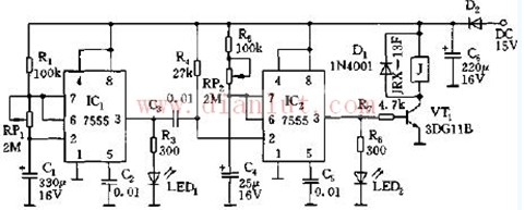
As shown in the figure, the controller is composed of two 555 cores. IC1 and R1, RP1, C1, etc. constitute an astable multivibrator t charge = 0.693 (R1 + RP1) C1, t put = 0.693RP1C1, T = t charge + t put = 0.693 (R1 + RP1) C1, IC1 A square wave with alternating high and low levels of output. Control IC2 monostable trigger delay circuit, that is, when the output of IC1 transitions from high level to low level, IC2 starts to flip set, timing, timing time, ie monostable transient stability pulse width Td=1.1(R5+RP2)C4, adjust RP2, make the fan turn for about 10 minutes, stop for 0.5-1 hour, brake cycle, realize automatic timing control. HuiZhou Superpower Technology Co.,Ltd. , https://www.spchargers.com