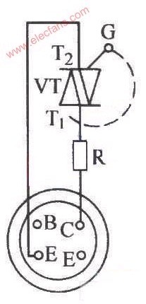
The figure below shows a schematic diagram using a digital multimeter test. Turn it to the NPN file, first let the G pole of the bidirectional thyristor VT open, and then pass through the current limiting resistor R (about 330Ω) to the "C" hole of the hFE socket, and the T1 pole is inserted into the "E" hole through the wire. The role of resistor R here is to prevent overloading of the hFE line. At this point, the digital multimeter displays a value of "000", indicating that it is in the off state. Then use a wire to short the G pole to T2, and the multimeter number immediately changes from "578", indicating that it has been turned on. The picture on the right is a verification circuit for the bidirectional thyristor. Different from the left picture, the T1T2 is switched over, and the G pole is still touched by the C pole through the wire. At this time, the digital multimeter display value changes from "000" to "428". This proves that the triac can be guided in two directions. Pass, the quality is good. Uniboot LC Patch Cord ShenZhen JunJin Technology Co.,Ltd , https://www.jjtcl.com