EPS basic working principle similar to the backup UPS or inverter, that is, when the electricity is normal, the electricity through the EPS mains bypass directly to the load, when the utility power, EPS switch to the battery inverter power supply to the load. Applicable to emergency panel lights and the like, you can adjust the control current to reach the emergency control of the voltage, control energy.
For most in the lighting industry industry there is a very real learning curve as we explore the intricacies, applications, limitations and potential of this amazing light source. Despite the curve, use of LED lighting for general lighting purposes is rapidly growing. Its popularity is not a mystery. LED technology is continually
improving. LEDs offer long life and high efficiency, have low operating costs and are lead and mercury free.
As with other types of lighting, LED lighting must meet the life safety code requirements for emergency illumination. LED fixtures serving as emergency units
must, therefore, provide at least 90 minutes of emergency lighting. Philips Bodine emergency LED drivers and emergency lighting inverters allow these fixtures
to meet or exceed code.
LED Emergency Driver LED Emergency Driver,LED Emergency Lights,Emergency Light,LED Warning Lights ShenZhen Fahold Electronic Limited , https://www.fahold.com
IntroducTIonAs the electronic content of automobiles conTInues to increase, designers of electronic control modules are challenged to deliver improved performance with an increasingly limited power budget. Modern cars include mulTIple electronic systems such as stereo and infotainment systems, wipers, car lighting systems, safety equipment such as air bags, and more. Given the cumulative demand these systems place on the automobile battery, designers must reduce the power consumption of each electronic system as much as possible, especially when the car ignition key is off and the car is parked.
Frequently, the battery has to supply quiescent power for multiple system operations when the automobile is off. To reduce power consumption during this condition, several power-saving modes have been introduced into the power-management blocks: shutting down the clock to the microprocessors, and disabling the converter circuits through the enable inputs are two common examples. There are, however, devices and functions—such as remote keyless entry (RKE) and security systems—that should always remain on, whether the power is supplied by the alternator or the battery. Figure 1 shows a typical power-supply module for air bags.
This application note presents a circuit using the MAX15006 / MAX15007 linear regulators for reducing the quiescent current of automotive air-bag applications. In addition to offering an ultra-low quiescent current, these devices are capable of withstanding load dumps up to 45V, making them ideal for the harsh operating conditions of automotive environments. Additionally, they feature a low dropout voltage, wide input voltage range, thermal and short-circuit protections, and an enable input, making them particularly well suited for power-supply modules in automotive air bags . 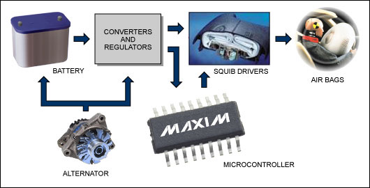
Figure 1. A typical power-supply module for air bags.
Operation of Supplemental Restraint Systems (SRS) An air-bag system or supplemental restraint system (SRS) is designed to provide additional protection for front-seat occupants when used in conjunction with a seat belt. An electronically controlled, mechanically operated system, SRS operates as follows: The system remains out of sight until activated in an accident that is determined by crash and safety sensors mounted on the vehicle. When an impact of sufficient force occurs, these sensors close their contacts, completing the electrical circuit and inflating the air bags . When not activated, the system is monitored by the air-bag diagnostic monitor, and system readiness is indicated by the lamp located on the instrument cluster.
As the diagnostic monitor is always on, the devices used to supply power must have a very low quiescent current. Also, during impact the terminals of the alternator may become detached from the terminals of the battery, which results in a load-dump condition. Variations in the supply may be high even during normal condition.
The MAX15006 / MAX15007 offer multiple features—such as an ultra-low quiescent current, wide input voltage range, and load-dump protection up to 45V—that make them perfectly suited for power-supply modules in automotive air bags. They can be used as-is without any external components for most applications that require a maximum current of 50mA. However, the total monitoring system for air bags requires a current of more than 100mA, and a current of not more than 200mA is required to check the readiness of the air bag igniter. Therefore, we need to increase the output current of the MAX15006 / MAX15007, which can be accomplished with an external pass transistor.
Increasing the Output Current Capability of the RegulatorThe minimum current required to cause ignition in the air-bag ignition circuits is 1.2A. The power requirements of the air-bag ignition circuit are supplied by both the switching regulators (buck and boost converters) and the linear regulator. However, the current requirement for the monitoring system (sensors, ADCs, igniter-readiness monitoring, etc.) is about 150mA, which is more than the maximum current that can be supplied by the linear regulator (MAX15006 / MAX15007).
The current capability of the linear regulator can be increased by using an external pass transistor. To increase the output current of the linear regulator, a pass transistor can be connected between the input and output as shown in the schematic below (Figure 2) .¹ This circuit increases the output current to 150mA. 
Figure 2. This circuit adds an external pass transistor to the MAX15007 to achieve sufficient output current (150mA) to supply an air-bag monitoring system.
Take R1 as 1Ω and R3 as 2.2Ω so as to keep the power dissipation to a minimum. Also, decreasing the value of R1 below 1Ω may increase the probability of thermal runaway of the PNP transistor. Initially, when there is no output current, the external pass transistor also does not conduct any current. As current gradually increases, it produces a drop of about 0.6V across the diode, causing the diode to start conducting. This conduction then provides enough voltage drop across the base-emitter junction to bring the PNP transistor also into conduction, thereby supplying the extra current required by the load. The purpose of R2 is to compensate for the high dynamic impedance of the diode at low current settings. Note that the external pass transistor is turned off when the load current is less than 25mA. The values ​​of the resistors can be changed to increase the amount of current supplied by this circuit.
Selecting an Output Capacitor for StabilityWith the external transistor connected in the circuit, the output voltage is not stable with 2.2µF of output capacitance as specified in the data sheet. This is because of the increase in the gM of the regulator, which results in an increase in the unity-gain frequency. This increase occurs because:
Unity-gain frequency ∠gM
To maintain the unity-gain frequency at the same value for which it was stable, the output capacitor has to be increased by the same amount as that of the increase in the gM. This increase in gM can be obtained by knowing the current gain resulting from the additional circuitry.
The current gain due to external circuitry can be approximately calculated using small-signal approximation of the circuit (Figure 3). 
Figure 3. To determine the required output capacitance, we must calculate the current gain of the external circuitry.
Let ΔI be the assumed change in the load current through the regulator when no external pass transistor is connected. Now, with the external pass transistor connected, let there be current change of K ΔI through the PNP pass transistor. Hence, the total change in the load current due to the external pass transistor is ΔI + K ΔI, ie, (1 + K) ΔI. Therefore, gM is increased by (1 + K) times. So, to maintain the same unity-gain frequency, output capacitance also has to be increased by (1 + K) times.
In our circuit, the value of K is obtained by the following equation: 
Considering the practical issues due to parasitics, the required value of capacitance is 5.45 times the minimum value specified in the data sheet. Hence, a capacitance of 12.2µF is connected at the output to stabilize the system with this external pass transistor.
Figure 4 and Figure 5 below indicate the current supplied by the external pass transistor for a steady load current of 150mA and for a transient load current of 150mA, respectively. Channel 1 indicates the output voltage, and Channel 4 indicates the current supplied by the external pass transistor. The parameter indicated by Channel 2 is the voltage across the 1Ω resistance connected in series with the load, and hence it can be considered as the total load current. Therefore, out of the total load current of 150mA, 109mA is being supplied by the external pass transistor while the remaining 41mA is supplied by the regulator IC. 
Figure 4. Performance of the Figure 3 circuit with a steady 150mA load current.
Channel 1: Output voltage
Channel 2: Load current proportional to voltage across 1Ω resistance in series with the load
Channel 4: Current supplied by the external pass transistor
Figure 5. Performance of the Figure 3 circuit with a transient load current of 150mA.
Channel 1: Output voltage
Channel 2: Load current proportional to voltage across 1Ω resistance in series with the load
Channel 4: Current supplied by the external pass transistor
ConclusionBy incorporating multiple features demanded by automotive applications into a single IC, the MAX15006 / MAX15007 directly fit the needs of many up-to-date automotive applications, making life easier for automotive engineers. This application note has shown that with minimum external circuitry, these ICs can meet higher load current demands, thus widening their range of applications.

Ultra low quiescent current linear regulator for automobile airbag-Ultra-Low Q
Abstract: This reference design shows how to increase the output current of the MAX15006 / MAX15007 linear regulators to meet the power-supply requirements for an automoTIve air bag.