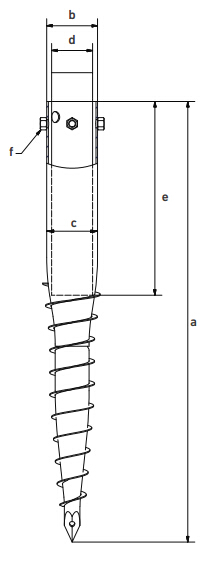
N series Ground Screw/Ground Screw Pile,ground Spike,ground screw pile foundation ,screw pile :Threaded Bolts fasten, No Flanges,one ,three or four bolts fixed .Including not galvanized ground screw,hot dip galvanized ground screw.
Available in the following diameters and length :
Diameter :68 mm,76 mm,89 mm,114 mm ,140mm,219mm
Length of N Ground Screw pile (mm) : 800,1000,1200,1500,1800,2000,2500,3000,5000 and requested length
Nut aperture for N series ground screw : 3-M 10/12/14/16
Surface treatment : Hot Dip Galvanized ,DIN EN ISO 1461-1999 ,average thickness of coating more than 80 micron
Range of Application : Solar power system,fence, timber construction ,farm and garden fence ,umbrella basement ,advertising board and banner ,lighting pole &
Production charting : Cutting pipe to he standard length ,forming the pipe according to design ,welding and assemble blade,flange,nut , acid pickling ,hot dip galvanize ,QC, Packing ,shipments
Helix Ground Screw,Helical Ground Screw,Solar Mounting Ground Screw,Galvanized Steel Ground Screw,Helical Screw Piles BAODING JIMAOTONG IMPORT AND EXPORT CO., LTD , https://www.chinagroundscrew.com

Senior engineers share the experience of high frequency circuit design
High-frequency circuits are typically defined as those operating at or above 45 MHz to 50 MHz, especially when they constitute a significant portion—such as one-third—of the entire electronic system. These circuits require careful design due to their complexity and sensitivity to interference. The layout of high-frequency circuits is crucial, as it directly impacts signal integrity, noise levels, and overall performance.
One of the key strategies in high-frequency circuit design is the use of multi-layer PCBs. These boards help manage high integration and dense wiring while reducing electromagnetic interference (EMI). By using intermediate layers for shielding and grounding, designers can minimize parasitic inductance, shorten signal paths, and reduce crosstalk. A four-layer board can provide up to 20 dB less noise compared to a two-layer board, but higher layer counts increase manufacturing costs and complexity. Therefore, selecting the appropriate number of layers is essential for balancing performance and cost.
Another important consideration is minimizing bends in signal traces. In high-frequency designs, sharp corners should be avoided, and 45-degree angles or rounded arcs are preferred. This helps reduce signal reflections and improves the stability of the copper traces. Additionally, shorter trace lengths between device pins are critical. High-frequency signals tend to radiate more, making them prone to coupling with nearby components. Therefore, clock lines, DDR data lines, LVDS, USB, and HDMI signals should be kept as short as possible to minimize interference.
Reducing the number of vias is also beneficial. Each via introduces a small amount of distributed capacitance, which can degrade signal integrity. Minimizing the use of vias helps maintain signal speed and reduces the likelihood of errors. Parallel signal lines can cause crosstalk, so it's important to separate them or insert ground planes between them. When parallel routing is unavoidable, placing a ground plane on the opposite side of the board can significantly reduce interference.
In digital systems, clock signals are particularly sensitive to crosstalk due to their fast edge transitions. To mitigate this, clock lines should be surrounded by ground traces and grounded vias. Using low-voltage differential signaling (LVDS) for high-speed clocks can further reduce noise and improve signal integrity.
Each integrated circuit block should have a high-frequency decoupling capacitor placed near its power supply pin. This helps filter out high-frequency noise and stabilizes the power supply. Grounding is another critical aspect. Digital and analog grounds should be isolated to prevent high-frequency harmonics from interfering with sensitive analog signals. A single-point connection or a high-frequency ferrite bead can be used to connect them safely.
Avoiding looped traces is also important. Loops can act as antennas, picking up or emitting unwanted signals. If loops are unavoidable, keeping the area as small as possible is recommended. Impedance matching is essential to prevent signal reflections, which can cause overshoot and signal distortion. Maintaining consistent impedance along the transmission line and avoiding abrupt changes or sharp corners ensures better signal integrity.
For specific standards like USB, HDMI, LVDS, and DDR, strict routing rules must be followed. For example, USB and HDMI require differential pairs with precise spacing and width. DDR signals need equal-length traces and proper spacing to ensure accurate timing and minimal crosstalk. All these considerations contribute to a robust and reliable high-frequency circuit design.
Finally, maintaining a continuous ground plane is vital to prevent "ground bounce," which occurs when the ground path is broken or segmented. A solid ground plane ensures stable reference voltages and minimizes noise. Overall, high-frequency circuit design requires attention to detail, proper layout techniques, and adherence to best practices to achieve optimal performance.