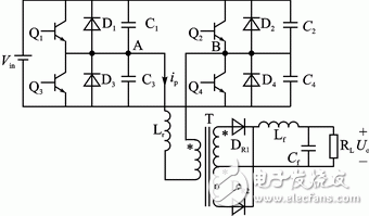
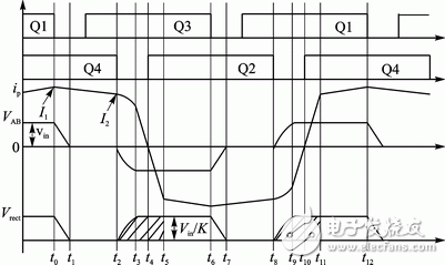
The system adopts voltage closed-loop control mode, and the regulator adopts variable parameter digital PI algorithm to realize complex algorithms and convenient and flexible phase shift control schemes that are difficult to implement in the simulation system. The experiment was carried out on a 2 kW prototype with a switching frequency of 2 kHz. introduction The phase-shifted full-bridge ZVS DCDC converter is one of the most widely used soft-switching circuits. As a phase-shifted full-bridge converter with excellent performance, the switching tubes of the two bridge arms are operated under the condition of zero voltage soft switching, the switching loss is small, the structure is simple, and the DC power supply is miniaturized and high-frequency. The development trend has been widely used in medium and high power DCDC conversion applications, and system digital control can further improve the reliability of the system. The digital system has complete programmability, which makes program modification, algorithm upgrade, and function migration very easy, and has obvious advantages over analog control. The digital control of DCDC converter is one of the current research hotspots. This paper analyzes the principle of the main circuit, and uses TMS320LF2407 as the main control chip to realize the full digital control of ZVS DCDC converter, and gives the experimental results. 1 main circuit topology and working principle The main circuit structure of ZVS PWM DCDC full-bridge converter is shown in Figure 1. The main waveform is shown in Figure 2. As can be seen from Figure 1, the circuit structure is similar to that of a conventional bipolar PWM converter. Q1, D1 and Q4, D4 form the leading bridge arm, Q2, D2 and Q3, D3 constitute the lag bridge arm; C1 ~ C4 are the resonant capacitance of Q1 ~ Q4 respectively, including parasitic capacitance and external capacitance; Lr is the resonant inductance, including the transformer The leakage inductance; T sub-party and DR1, DR2 constitute a full-wave rectification circuit, Lf, Cf constitute an output filter, RL is the load. Q1 and Q3 advance Q4 and Q2 respectively to a certain phase (ie, phase shift angle), and adjust the output voltage by adjusting the magnitude of the phase shift angle. It can be seen from Fig. 2 that in one switching cycle, the phase-shifted full-bridge ZVS PWM DCDC converter has 12 switching modes. By controlling four switching transistors Q1 to Q4, an amplitude of Vin is obtained at two points A and B. AC square wave voltage; after isolation and transformation of the high-frequency transformer, an AC square wave voltage with an amplitude of Vin/K is obtained on the transformer secondary side, and then an output rectifier bridge composed of DR1 and DR2 is used to obtain an amplitude of Vin. /K DC square wave voltage. This DC square wave voltage is passed through an output filter composed of Lf and Cf to become a flat DC voltage whose voltage value is UO=DVin/K (D is the duty cycle). Ton is the on-time and Ts is the switching period (Ts=t12-t0). The output voltage UO is adjusted by adjusting the duty ratio D. Figure 1 Converter main circuit structure Figure 2 main waveform of the converter As can be seen from the waveform diagram, the characteristics of the phase-shifted full-bridge circuit control method are: 1 During a switching period Ts, the on-time of each switch is slightly less than Ts/2, and the off-time is slightly larger than Ts/2. 2 In the same half bridge, the upper and lower switches cannot be in the open state at the same time, and each switch is turned off until the other switch is turned on to pass a certain dead time. 3 Compare the switching function waveforms of two pairs of switching tubes Q1, Q4 and Q2 and Q3 which are diagonal to each other. The waveform of Q1 is longer than 0~ Ton/2 time of waveform of Q4, and the waveform of Q2 is ahead of 0~ Ton/ of waveform of Q3. 2 time, so Q1 and Q2 are leading bridge arms, and Q3 and Q4 are trailing bridge arms.
LED Therapy Light High Power, include 3 wattages, 300w 500w 1000w, 300w with 50pcs led, 500w with 1000cs led, 1000w with 200pcs led.
Why use LED Therapy Light?
Red Light Therapy is a skin care treatment being offered as an alternative to physician-administered laser therapy.
Nost studies is involving red light therapy revolve around the treatment of acne, and of its ability ti get rid of wrinkle, while research is not yet conclusive on the benefits of red light therapy, studies suggest that concentrated red light is absorbed y the mitochondria in the cells and stimulates the generation of more collagen.
Led Therapy Light High Power Red Light Therapy ,Rechargeable Led Face Light,Led Therapy Light,Red Light Infrared Full Body Shenzhen Wenyi Lighting Technology Co., Ltd , https://www.wycngrow.com