FIRSTPOWER offers a full assortment of Industrial Batteries are built to last and deliver power when needed, thereby ensuring maximum life and optimum performance. Ideal for mobility, golf carts and a range of industrial applications such as walkers and stackers etc.
We welcome orders with "FirstPower" brand; We are also flexible to accept orders on OEM basis. Contact us now! Your partnership with FirstPower will prove worthy of it.
Industrial Battery,Rechargeable Industrial Use Batteries,Industrial Lithium Battery Firstpower Tech. Co., Ltd. , https://www.firstpowersales.com
Introduction The MAXQ7665 microcontroller evaluation (EV) board includes a serial port to JTAG connection for programming and debugging. IAR Embedded Workbench is connected to MAXQ7665 through JTAG and used during debugging. This quick start completes the evaluation board data and records the use of the IAR toolbox.
IAR Workbench Introduction IAR Embedded Workbench is an integrated development environment for the MAXQ7665 microcontroller and other MAXQ® microcontrollers. The IAR toolbox includes a text editor, C language editor, serial download, and a powerful debugger.
The IAR workbench is installed through the IAR website, and the IAR Embedded Workbench is installed on the PC. Select the "Chip manufacturer" box on the IAR homepage. Then, select Maxim / Dallas Semiconductor from the "Please select chip manufacturer" drop-down box, and click the OK button. A new page appears, which includes hyperlinks. Click "IAR Embedded Workbench for Maxim MAXQ", another page appears, it contains the highlighted Download box. Select "30–day evaluaTIon version". A product registration page appears. You must complete this page to start downloading Maxim MAXQ's IAR Embedded Workbench. Once the download is complete, you can use this evaluation version of the embedded workbench within 30 days, and you will need to purchase a permanent license later.
After the IAR toolbox is installed, the MAXQ7665 function files created during installation include: maxq7665_A64K.ddf maxq7665_A128K.ddf lnkmaxq7665_A64K.xcl lnkmaxq7665_A128K.xcl lnkmaxq7665_cbl_A64K.xcl maxq7665.Axmaxq7665 Config folder: b) Config / Devices folder: c) Include folder: Copy the MAXQ7665 evaluation board folder from the src directory of the evaluation board CD to the default path C: \ Program Files \ IAR Systems \ Embedded Workbench 4.0 EvaluaTIon Version \ MAXQ \ src, or copy it to the installation path of the IAR tool.
The hardware installation connects the MAXQ7665 evaluation board and AC adapter. The RS-232 serial cable is used to connect the PC to the DB-9 connector of the evaluation board, which is labeled PC RS232 JTAG.
The IAR work area file organization IAR structure requires an engineering work area. This workspace can include C language and assembly source code files to achieve specific tasks. Each project can be compiled, debugged and run separately. Figure 1 below shows the working area of ​​the MAXQ7665 evaluation board and the projects it includes. Please refer to the IAR Embedded Workbench User's Guide in the Help menu of the IAR Embedded Workbench application for details. 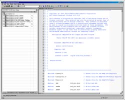
View detailed picture Figure 1. This workspace of MAXQ7665 lists the projects included in the software.
To set IAR project options, you must set the options for each project in the workspace. If a new project is added, its options must be configured. The sample project included in the evaluation board has been configured with various options. If you need to view or change project options, right-click the highlighted project in the Overview screen, or click the project tab at the bottom of the screen to make the project "active." The project name will be displayed in bold, as shown in Figure 1. Next, in the Project menu, select OpTIons, the following screen shot appears. You can set options for each category, as shown in Figure 2. 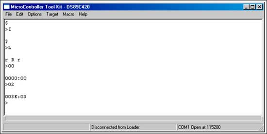
Figure 2. The project options menu allows you to configure the options for each project.
The JTAG serial port is the only option that needs to be set for the example project. If JTAG is selected, the screenshot shown in Figure 3 will appear. In this example, we use COM1 as the communication port from the PC to the MAXQ7665 EV kit. If you need to use a different port, change COM to the corresponding serial port. 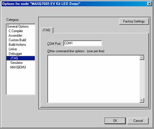
Figure 3. The communication between the IAR toolbox and the MAXQ7665 is established through the JTAG interface.
When building a new project or target application for the MAXQ7665 evaluation board, certain important options must be set. Use special files to build the MAXQ7665 optional linker and debugger configuration.
IAR linker option In the OpTIons window, select the Linker category and the Config tab, as shown in Figure 4. In the XCL file name section, select the "Override default" box and find the lnkmaxq7665_A64K.xcl linker file in the configuration directory. 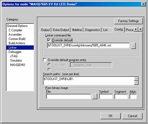
Figure 4. Configure linker options for the project on this screen display.
IAR debugger options When setting debugger options, select the Debugger category. Select "Use device description file" (Figure 5) in "Device description file" and find the maxq7665_A64K.ddf file in the configuration directory. 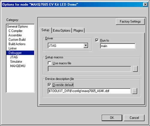
Figure 5. On this screen display, you can configure debugging options.
The quick start CD of the example project evaluation board includes several example projects. The example code demonstrates the function of the MAXQ7665 and the evaluation board. Example projects are programs that can be compiled, linked, and run. The user can create a workspace and project, and then copy the example project code section to build the application. The following is a brief description of the example project.
ADC This project contains software to build the MAXQ7665 analog-to-digital converter (ADC). It is easy to modify the ADC parameters. If interrupts are used, these parameters can be passed to the ADC_Convert_Int function. When the conversion is complete and the data is ready, the ADC data will be returned in the interrupt service routine. If ADC polling is used, comment out the ADC_Convert_Poll function. When the ADC has completed the conversion and the data is ready, the ADC conversion value is returned to the function.
The CAN CAN project contains software to build a CAN controller. The example project sets global CAN parameters, and then establishes a receiving and sending message center. If you need to verify this operation, you can set the CAN controller to autobaud (loopback) mode to transfer CAN data from the sending message center to the receiving message center.
DAC This project contains functions to configure a digital-to-analog converter (DAC), which can generate a continuous sine wave output from each DAC.
LED Demo The LED demo project sets up and clears the MAXQ7665 port bit that drives the LED. The result is a simple flow signal simulation using LEDs.
Temperature conversion MAXQ7665 contains an internal temperature sensor, the evaluation board has two external temperature sensing devices. The temperature conversion project can measure internal or external temperature.
The timer timer project demonstrates the establishment of 8-bit and 16-bit pulse width modulation timers with adjustable frequency and duty cycle. A delay timer using timer 0 is also provided, with an accuracy of 1 ms.
UART The UART project supports the interface between the evaluation board and the RS-232 serial port. MAXQ7665 sets UART parameters and controls serial data exchange.
The voltage monitor brightness adjustment monitor project contains demonstration functions and software that uses the brightness adjustment monitor detection circuit. The program sets the voltage threshold of the brightness adjustment interrupt; you can move the interrupt service routine breakpoint to the breakpoint required by the voltage to be measured. Then, the user presses a button on the PC board of the evaluation board to trigger the required brightness adjustment interrupt.
Start the IAR Embedded Workbench C: \ Program Files \ IAR Systems \ Embedded Workbench 4.0 \ MAXQ \ src \ MAXQ7665 EV Kit directory, or the directory where the source files are installed. Select the workspace file MAXQ7665 EV Kit.eww and click open.
This selection opens a MAXQ7665 evaluation board workspace, which contains several projects. Find the label labeled MAXQ7665 EV Kit LED Demo (bottom of the window; right-click) and highlight MAXQ7665 EV Kit Led Demo-Debug. If it has not been set, right-click and select Set as Active Project (displayed in bold on the screen).
Right-click again and choose Options. Store project settings here. Note: The serial port must be set. Select JTAG. Under COM Port, if you are not using COM1, enter the serial port used. Note: You must use COM #, not just the port number. Some notebook computers do not have an RS-232 port, but have a USB to RS-232 converter.
In the Project menu, select Rebuild All. If all files are correctly located, Errors: None and Warnings: None will be displayed in the message box.
After completing the steps described above and no errors, select Debug in the Project menu. Download the application code to the MAXQ7665 evaluation board.
Once the application file is downloaded, start the debugger in the "main" statement. In the Debug menu, click the Go command, the LED will simulate the flow signal.
Basic troubleshooting When trying to communicate with the MAXQ7665 EV kit, if an error message appears, you need to close and reopen IAR Embedded Workbench. If restarting the IAR does not solve the problem, try to disconnect the RS-232 cable connected to the evaluation board, power on again, and reset the evaluation board. Then, reconnect the RS-232 cable, power up, and open the IAR toolbox. If IAR cannot communicate with the MAXQ7665 EV kit, please refer to the advanced troubleshooting section below.
Advanced troubleshooting This section describes the steps to install and use Maxim's microcontroller kit (MTK) and debug the MAXQ7665 evaluation board via RS-232 connection. If IAR Embedded Workbench cannot be downloaded to the MAXQ7665 evaluation board, it needs to be debugged.
Required hardware and software Windows® PC with RS-232 port. Evaluation Kit for MAXQ7665 The Evaluation Kit for MAXQ7665 is equipped with a CD AC to DC converter and provides a 12V output. DB–9 to DB–9 RS-232 cable The installation CD of the MAXQ7665 evaluation board in the MTK catalog of software installation provides the MTK utility. Please run the SETUPEX.exe file to install the MTK application.
The hardware installation connects the MAXQ7665 evaluation board and the AC power adapter. Use a RS-232 serial cable to connect the PC to the DB-9 connector on the evaluation board, which is labeled PC RS232.
Launch the MTK utility Once the application is installed, open it and select DS89C430 from the drop-down menu. The device is used for communication between the RS-232 port of the PC and the JTAG connection of the MAXQ7665.
Set MTK options, select Options, then Configure Serial Port. Enter the serial port used and set the rate to 115,200 baud rate. Also select "Toggle DTR on connect / disconnect", "Save working directory on exit" and "Save COM Port Settings on Exit" (if these settings have not been made yet).
Connect to the MAXQ7665 evaluation board and select Target, then "Open COMx at 115200 baud", where x is the serial port configured in the above option. Press the Enter key on the keyboard to test the RS-232 interface. Each time the Enter key is pressed, the MAXQ7665 evaluation board should respond with the prompt “>â€. If this step is normal, it indicates that the microcontroller on the evaluation board can recognize the input and is ready to receive the input. If this step is not normal, please refer to the No Prompt section below.
There is a simple way to connect to the MAXQ7665 debug engine to determine the state of the MAXQ7665: "Get" all internal registers. The Get command sends a few basic commands to the debug engine to make the MAXQ7665 send all its internal registers. The protocol.txt file in the Quick Start CD in the MTK directory contains this command. Use the following command to get all the registers. Make sure to use the uppercase key (CAP), because MTK is case sensitive. The parentheses are comments.
> I (Initialize the debug engine, press the Enter key.)
> D (Enter the debug background mode and press Enter.)
> E (Enter the debug mode and press enter.)
> G (To get all registers, press the Enter key.)
If the MAXQ7665 is working properly, it should respond with the register map shown in Figure 6. Note that the register starts with Module 0 Register 0, then Module 0 Register 1, and so on. Also note that multiple commands can be combined on one line. For example,> IDEG will produce the same result. 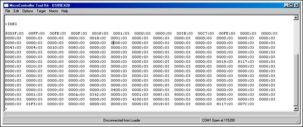
Figure 6. If the MAXQ7665 is configured correctly, the register map should start with Module 0, Register 0.
From the above register map, the first register of Module 0 and Index 0 M [00,00] is Port 0 Output Register (PO0). The power-on reset value (POR) of this register is 0x3F, which is correct. The following two registers are Port 1 M [01,00] and Port 2 M [02,00] output registers, and their POR value is 0xFF, which is also correct.
If you do not get the register map shown in Figure 6, but get the register map shown in Figure 7, then press and release SW10 to reset MAXQ7665. Once this operation is performed, repeat the IDEG command and you should get the register map shown in Figure 6. Note that the register map shown in Figure 7 is also acceptable to the debug engine. 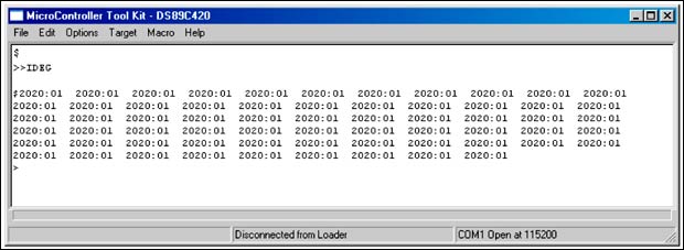
Figure 7. Another Get register map
If the previous steps are successfully completed, the communication link from the PC to the microcontroller JTAG to the MAXQ7665 debug engine is working properly. You should be able to close the MTK communication port and close the MTK application. IAR Embedded Workbench can download the code and debug the application code of the MAXQ7665 evaluation board.
Debug engine status The debug engine also returns its status and the above data. For example, the first register M [00,00] is 003F: 03. The four characters on the left are the hexadecimal value of the register. Regardless of the register length, the returned data is always 16 bits wide. In this example, there is a colon and 03. 03 is the handshake signal between the host and the debug engine. In this example, 03 means debugging is effective. The following table lists the possible states. Status Condition 00 Default Condition. Background mode or debug engine inactive (MAXQ7665 in reset) 01 Debug Idle. Ready to receive data from the host (ready for download and debug) 02 Debug Busy. Debug engine is busy without valid data (Password Lock State) 03 Debug Valid. Debug engine is busy with valid data (ready for download and debug)
Troubleshooting If the above operation does not work, or the result is different from the one shown here, then the following operations are required.
If there is no prompt, if you cannot get a prompt from the MAXQ7665 evaluation board, disconnect the RS-232 cable from the evaluation board and unplug the DC power plug. Then, reconnect the RS-232 cable and DC power plug. If necessary, repeat this process. Also make sure that the serial port selection in the Options menu is the port you are using. If you need to know the available serial ports, run the following application. Open the control panel System application and select the Hardware tab. Select Device Manager and Ports (COM and LPT) to view the available serial ports.
Invalid data-busy debugging Sometimes the data returned by IDEG is similar to the following data, for example, the debug engine status data contains: 02. This value usually indicates that the MAXQ7665 password is locked to prevent erasing the flash memory and prevent any communication between the IAR Embedded Workbench and the MAXQ7665. Please refer to Figure 8. 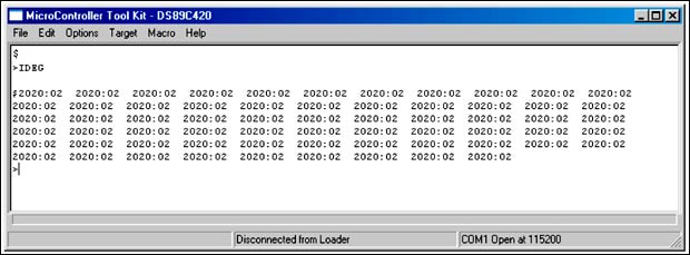
Figure 8. The ID02 on the IDEG screen indicates that the MAXQ7665 password is locked.
Erasing the MAXQ7665 flash memory can use the MTK interface to erase the MAXQ7665 flash memory. Figure 9 details the steps required for erasure.
Figure 9. The screen shows the steps to erase the MAXQ7665 flash memory. > I (Type I. Initialize the debug engine and press Enter.) $ (Debug engine replies.) > L (Type L. Enter the bootstrap loader and press Enter.) r R r (Loader replies.) > 00 (Type 00. Press Enter.) 0000: 00 (Loader replies.) > 02 (Type 02. Erase the flash and press Enter.) 0000: 02 (Debug engine replies still busy if unsuccessful.) 003E: 03 (Debug engine replies debug valid. Flash is erased.)
If the above steps are not successful when erasing the flash memory, the entire process is repeated. Remove the DC power supply, press the reset switch, and enter the above command. If the erase is successful, you should be able to "Get" all registers successfully using the IDEG command described above. IAR Embedded Workbench should be able to download application code.
Support application engineers provide you with MAXQ7665 evaluation board support. For email support, please contact the Maxim Support Center. To contact the Maxim office in North America, please call toll-free: (800) 998-9872 (English only).
MAXQ7665 Evaluation Board Quick Start
Abstract: This application note is a quick start. It explains how to install and configure IAR Embedded Workbench®. In addition, it provides brief instructions to compile, link, and debug several example projects in the MAXQ7665 microcontroller evaluation kit. The troubleshooting section can help determine the working condition of the evaluation board.