Abstract: Fuel cell vehicle is an emerging clean energy vehicle. In order to improve the efficiency and reduce the volume and weight of high-power DC/DC converters for fuel cell vehicles, a new soft-switching Boost converter is proposed. The working principle of the converter has developed a 20 kW experimental prototype. The results show that the new soft-switching Boost converter is simple in structure and excellent in performance, and is very suitable for use in fuel cell vehicles, battery electric vehicles and uninterruptible power supply (UPS) systems. Bipolar transistors (IGBTs) are used as high voltage, high power applications for main power devices. This article refers to the address: http:// Plated Plastic Housing Coffee Grinder Coffee Mill Grinder,Coffee Grinder Machine,Automatic Coffee Grinder,Plated Plastic Housing Coffee Grinder FOSHAN FORTUNE ELECTRICAL APPLIANCE CO.,LTD , https://www.coffelady.com
Key words: converter; fuel cell vehicle; soft switch
1 Introduction Fuel cell vehicle power systems often require a high-power DC/DC converter to connect the fuel cell to the power drive system and the energy storage system for power regulation, and the boost ratio of the high-power DC/DC converter is generally small. Usually no isolation is required. Comprehensive analysis of the existing DC/DC converter structure, non-isolated Boost converter structure is simple, high efficiency, continuous input current, very suitable for fuel cell vehicle power regulation.
However, in the conventional high-power hard-switching converter, there is a current tailing phenomenon when the IGBT is turned off, and the turn-off loss is very serious. Conventional soft switches mostly use the resonance principle to change the current (voltage) in the power tube according to a sinusoidal or quasi-sinusoidal law. When the current naturally crosses zero or the voltage is zero, the power tube is turned on or off, thereby reducing the power tube switching loss.
A new soft-switching Boost converter is proposed for the turn-off loss of high-power IGBTs, which effectively reduces the turn-off loss of the main power tube and realizes the zero-voltage and zero-current switching of the auxiliary power tube. Compared with other soft-switching Boost converters, the converter has a simple circuit, small size, light weight and high efficiency, and can work reliably in the full load range, which is very suitable for fuel cell vehicles.
2 capacitor buffer soft switch Boost converter
2.1 Circuit Structure For high-power Boost converters using IGBTs, the turn-off losses of power transistors are usually much larger than their turn-on losses. A SiC diode with a reverse recovery current of almost zero can effectively reduce the power transistor turn-on loss. The capacitor buffer soft switch is mainly used to solve the turn-off loss of the main power tube V1 in the Boost converter. During V1 turn-off, the capacitor snubber circuit slows down the voltage rise rate of V1 and reduces the current smearing when V1 is turned off, thus effectively reducing the turn-off loss of V1. Figure 1 shows a capacitively buffered soft-switching Boost converter. Among them, VD1 is the main diode, L1 is the main boost inductor, and C1 is the output filter capacitor. The capacitor buffer circuit is composed of auxiliary switching tubes V2 and V3, auxiliary diodes VD2 and VD3, and snubber capacitor C2. 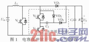
Figure 2 shows the main operating waveforms of a capacitively buffered soft-switching Boost converter. 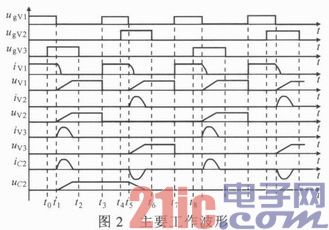
2.2 Working principle analysis In order to facilitate the analysis of the working state of the circuit, it is assumed that: 1 all components in the circuit are ideal; 2L1 is large enough, the current is basically kept unchanged by IL1 in one switching cycle; 3C1 is large enough in one During the switching cycle, the ripple of the output voltage is negligible and the output voltage remains substantially Uo. Based on the above assumptions, each soft open pipe duty cycle of the circuit can be divided into the following eight states:
State 1 (t0~t1) Before t0, V1 is turned on, V1 terminal voltage uV1=0, current iV1=IL1, V2, V3 and C2 terminal voltages uV2, uV3, uC2 and currents iV2, iV3, iC2 are zero. At time t0, V3 zero voltage is turned on, and V3 is turned on does not affect the normal operation of the circuit;
State 2 (t1 ~ t2) At time t1, V1 is turned off. Since V3 is turned on, part of IL1 flows through V1, a part flows through VD2, and V3 charges C2 until C2 is charged to Uo. This charging behavior reduces the tail current of V1, slows down the uV1 rise rate, and greatly reduces its turn-off loss. During this period, uV3=0, uV2 changes with uV and rises to Uo;
State 3 (t2 ~ t3) At time t2, V3 zero voltage, zero current is turned off, and V3 is turned off does not affect the normal operation of the circuit;
State 4 (t3 ~ t4) At time t3, V1 is turned on, and the V1 turn-on process is not affected by the buffer circuit. During the turn-on process, uV3 remains at zero, uV2 drops to zero with uV1, and uC2 remains unchanged.
State 5 (t4 ~ t5) At time t4, V2 zero voltage is turned on, and V2 is turned on does not affect the normal operation of the circuit;
State 6 (t5 ~ t6) At time t5, V1 is turned off again. Since V2 is turned on, part of IL1 flows through V1, and a part flows through V2, C2, and VD3 discharges to the load until uC2=0. The C2 discharge not only improves the efficiency of the converter, but also reduces the V1 tail current and slows the uV1 rise rate. During this period, uV2=0, uV3 changes with uV1 and rises to Uo;
State 7 (t6 ~ t7) At time t6, V2 zero voltage, zero current turn off, V2 turn off does not affect the normal operation of the circuit;
State 8 (t7~t8) At time t7, V1 is turned on again. During this period, uV2=0, and uV3 changes with uV1 and continues to decrease to zero. The next soft-switching process will begin at t8.
2.3 Soft Switch Implementation Conditions As can be seen from the above analysis, the soft switch implementation condition is very simple. As long as V2 and V3 are guaranteed to be turned on before V1 is turned off, it can be turned off before V1 is turned on again. V2, V3 use a constant duty cycle to achieve C2 charging (V3 turn-on) and discharge (V2 turn-on). The V1 turn-off time is synchronized with the turn-on time of V2 and V3. By adjusting the turn-on time of V1, it can be adjusted. Empty ratio.
Usually the duty cycle of the Boost converter is not very high. C2 can charge or discharge before V1 is turned on, and does not impose any practical limit on the duty cycle of V1. In addition, the use of a small capacity of C2 can achieve a reduction in turn-off loss, a small capacity C2 charging speed, and no limit on the duty cycle, while helping to reduce the auxiliary circuit conduction loss. The choice of C2 needs to consider two factors: 1 to reduce the conduction loss of the auxiliary device, C2 should be minimized; 2 to minimize the V1 turn-off loss, C2 must be large enough to slow the voltage rise rate when V1 is turned off. . Let uV1 expect the rise time to be Δtdes, then:
C2=ImaxΔtdes/Umax (1)
Where: Imax, Umax are the maximum current and voltage of V1.
3 Experiment To comprehensively understand the capacitor buffer soft switching circuit, a capacitor buffer soft-switching Boost converter with a switching frequency of 60 kHz and a power of 20 kW was designed and fabricated. For design and debugging, V1, V2 and V3 all use IGBT module CM300DU-12NFH. The maximum set of emitter voltage is 600 V and the maximum collector current is 300 A. The internal parasitic inductance of the module is low and the switching frequency can reach 60 kHz. VD1, VD2 and VD3 select C3D20060D SiC diode, its rated voltage and current are 600 V, 20 A, and the reverse recovery is approximately zero. L1 = 250 μH, C1 = 300 μF, Δtdes = 0.5 μs, C2 = 0.15 μF.
The experimental prototype soft switch is implemented by the microcontroller ATMega128. The converter input current is collected and converted to a voltage of 0 to 5 V to the microcontroller A/D port, which the microcontroller uses to change the V1 duty cycle. The duty ratio of V2 and V3 is fixed to be constant, and the on-time is slightly larger than Δtdes. Before V1 is turned off, the V2 and V3 control signals are valid, and the control signals of V2 and V3 are 180° out of each other. After C2 is charged or discharged, V2 and V3 turn on without any side effects on the circuit, as long as it is turned off before V1 is turned on again. 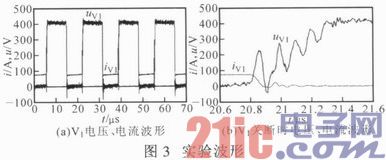
Figure 3a shows the V1 voltage and current waveforms in the capacitor-buffered soft-switching Boost converter. It can be seen that when V1 is turned off, the terminal voltage rise rate is slowed down. Figure 3b shows the detailed voltage and current waveforms when V1 is turned off. It can be seen that the capacitor snubber circuit reduces the tail current of V1, slows down the voltage rise rate when V1 is turned off, and thus reduces the turn-off loss of V1. The experimental results further verify the performance of the capacitive buffer soft-switching circuit and are consistent with the theoretical analysis results.
4 Conclusions A novel capacitive buffer soft-switching high-power Boost converter for fuel cell vehicles is designed. The converter uses a capacitor-buffered soft-switching circuit to greatly reduce the turn-off loss of the main power tube. The recovery of the silicon carbide diode reduces the main power tube conduction loss. Unlike soft-switching converters, capacitive-buffered soft-switching circuits eliminate the need for bulky additional inductance, with the addition of two insulated gate bipolar transistors, two diodes, and a capacitor. The converter circuit is simple in design, easy to control, small in size, light in weight and high in efficiency, and is very suitable for a fuel cell vehicle, a battery electric vehicle and an uninterruptible power supply system.