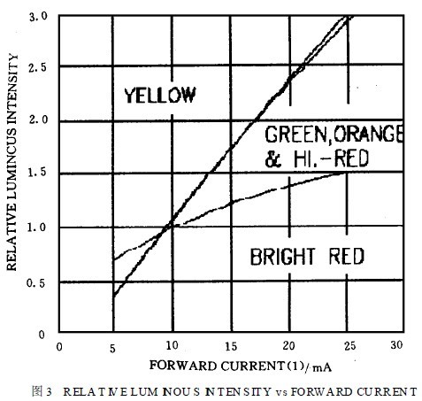
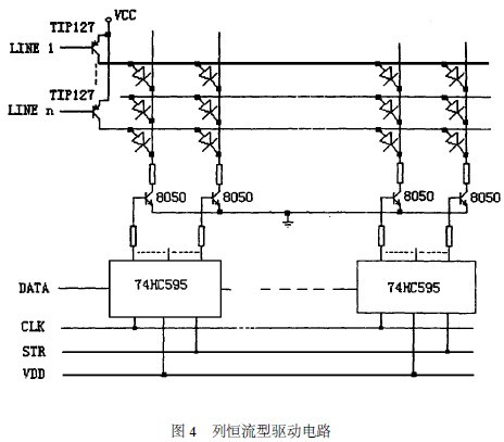
1 Introduction LED display screen is a new type of information display media that has been rapidly developed around the world in the late 1980s. It uses a dot matrix module or pixel unit composed of light-emitting diodes to form a large-area display screen with high reliability, long service life and strong environmental adaptability. It has high performance and price ratio and low cost of use. It has been widely used in the field of information display. The LED display mainly includes an array of LEDs, a driving circuit, a control system and a transmission interface, and corresponding application software, etc., wherein the design of the driving circuit is good or bad, and the display effect, manufacturing cost and operating performance of the LED display are A very important role. Therefore, it is necessary to design a control drive circuit that satisfies the requirements of the control drive while using fewer devices and lower cost. This paper analyzes the design of the conventional drive circuit and proposes the design of the constant current drive circuit. 2 LED display conventional drive circuit design The design of the LED display driver circuit, in conjunction with the control system used, is generally divided into dynamic scanning type driving and static latch type driving. The following is an example of the design of the dynamic scanning type driving circuit for analysis: The dynamic scanning type driving method means that four rows, eight rows, and 16 rows of n-th LEDs on the display screen share a set of column driving registers, and the time-division work of the row driving tubes makes the lighting time of each row of LEDs total. 1/n of time, as long as the refresh rate of each line is greater than 50 Hz, people can see a complete text or picture by using the visual persistence effect of the human eye. Conventional driver circuits are generally designed with a serial-integrated integrated circuit chip such as the 74HC595 or MC14094 as a column data latch, a small power N PN transistor such as 8050, and a Darlington transistor such as T IP127. As a row scan tube, its circuit is shown in Figure 1. For example, a monochrome dot matrix, 16 rows × 64 columns is used as a basic unit, and eight 74HC595, 64 8050 and 16 row scanning tubes are required. The working principle is as follows: Eight 74HC595 are cascaded to share one serial clock CL K and data latch signal STR. When the data to be displayed in the first line is shifted into the 74HC595 after 8×8=64 CL K clocks, a data latch signal STR is generated to latch the data in the latter latch of the 74HC595. The 8050 corresponding to each output bit will be saturated or turned off; at the same time, the line scan control circuit generates a signal to make the first row of scan tubes turn on, which is equivalent to the positive end of the first row L ED is connected to the high level, obviously the first row of LEDs The tube is turned on and off depending on the signal latched in the 74HC595; while the first row of LED tubes is lit, the next line of data is displayed in the 74HC595, which is then latched and simultaneously controlled by line scan. The circuit turns off the first row of scan tubes and turns on the second row, so that the second row of LED tubes is lit... and so on. When the sixteenth line is scanned, it returns to the first line, as long as the scanning speed is high enough. A complete text or image can be formed, and its working timing is shown in Figure 2. 3 defects in conventional drive circuits Although the design structure of the conventional driving circuit is relatively simple, there are two defects: (1) When a row driving tube is valid, the lighting current of all the LEDs corresponding to the row will flow through the row to drive the scanning tube, and the number of LED tubes in one row will follow the text to be displayed or The pattern is constantly changing, so the current flowing through the scanning tube has a large change, which will change the tube pressure drop; (2) The change of the LED tube causes the current to change, which will also affect the fluctuation of the power supply voltage value, which will affect the voltage across the first row of LED tubes, causing them to fluctuate with different display characters or graphics. Affects the uniformity of the brightness of the entire display. Therefore, the author designed a column constant current driving circuit, which can eliminate the influence of the fluctuation of the power supply voltage and the change of the voltage of the scanning tube on the brightness of the LED display. 4 LED display constant current drive circuit design Figure 3 shows the relationship between the relative brightness of the LED and the current flowing through it. [From the curve, it can be seen that within a certain forward current operating range, the luminance of the LED is similar to the current flowing through it. In proportion, it is a current-driven device. Therefore, as long as the current flowing through each LED tube is guaranteed to be constant, the brightness can be ensured. As can be seen from the working principle of the conventional drive circuit, since the row and column drive tubes are all in a saturated state and cannot control the magnitude of the current, the fluctuation of the applied power supply voltage and the pressure drop of the line scan drive tube are changed. Etc., directly affects the current flowing through the LED tube, that is, changes its display brightness. If the column drive tube is changed from the saturated state to the linear amplification state and becomes a constant current type drive, the uneven brightness of the display screen caused by the above factors can be eliminated. The column constant current type driving circuit is shown in Fig. 4. When the power supply voltage VDD is stable, the high-level output voltage V of the 74HC595 is also stable. For example, when the power supply voltage VDD is 6V, V = 5. 9V. Therefore, when the output of a certain bit of the 74HC595 is high, the LED of its corresponding column will be illuminated, and the current flowing in it is approximately: As long as the values ​​of R 1 , R 2 and R 3 are reasonably selected, the current flowing through the LED can be kept constant, and the LED light-emitting diode can be operated at the optimum state of the forward current and the corresponding luminance. By using this column constant current driving mode, it can be achieved regardless of the number of LED tubes in a row, although the tube voltage drop of the row driving tube still changes, the power supply voltage VCC can also be changed, because each LED The current flowing through the LED is constant, thus ensuring the uniformity of the brightness of the LED display. 5 Conclusion Compared with the conventional conventional driving circuit, the LED display constant current driving circuit overcomes the defects of the conventional driving circuit with only minor modifications, and ensures perfect performance. The author uses the actual use of multiple display screens. Get the ideal display. Edit: Cedar Disposable surgical masks are made of nonwoven material, including filter layer, mask belt and nose cheek. They are generally disposable and can block particles larger than 5 microns in diameter.Especially surgical masks, the resistance to bacteria and viruses is strong, can effectively filter the virus or bacteria attack the respiratory tract, also can avoid the virus and bacteria to others. Disposable medical mask,Mask medical,Medical masks,Facemask YFJ TECHNOLOGY (HK) CO.,LIMITED , http://www.yfjpower.com


And the ordinary mask is not generally disposable, the material is more, there is cotton mask, there is also non-woven cloth mask.The main effect is to keep warm more, still can block the dust droplet of part, but the ability of general antivirus is lesser, cannot prevent bacterium or virus to invade respiratory tract.