Carbon Fiber FPV Drone Frame,FPV Drone TrueX Frame,Carbon Fiber FPV Frame Jiangsu Yunbo Intelligent Technology Co., Ltd , https://www.fmodel-ai.com
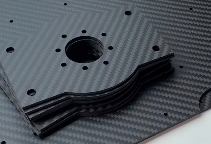
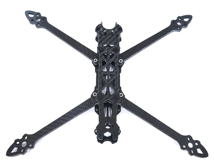
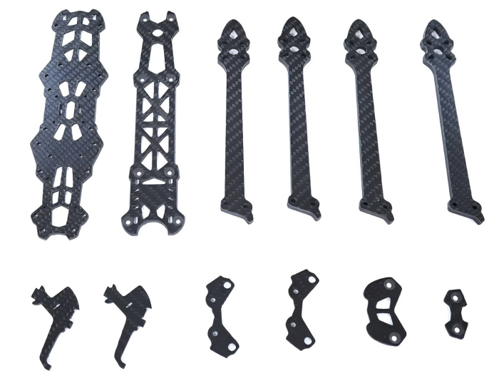
Mark4 V2 Mark4 7inch 295mm / 8inch 367mm / 9inch 387mm / 10inch 427mm 3K Full Carbon Fiber TrueX Frame for FPV Camera Kit Done:


Detailed steps and methods for patch antennas to solve diversity and multi-frequency problems
In the world of handheld and portable wireless devices, such as smartphones and wearable electronics, microchips, patches, and wire antennas play a crucial role. These compact components are essential for integrating multi-band antenna arrays into small systems. However, while they solve the issue of space constraints, they also introduce challenges like reduced radiation efficiency, impedance mismatch, and interference from nearby objects or human bodies.
To tackle these issues, designers have started adopting innovative design and circuit techniques, transforming antennas into dynamic subsystems that can address many of the traditional design hurdles. This shift demands extensive simulation and analysis, which modern field solver software now effectively supports.
The move from traditional external whip or short antennas to chip and patch antennas is driven by several factors. Aesthetics and durability are key concerns, as external antennas are often seen as unattractive and prone to damage. From a performance perspective, smartphones typically require multiple antennas in the same frequency band to provide diversity, enhancing overall system performance. Moreover, multi-band devices—especially those supporting 5G standards—need dedicated antennas for each frequency band they operate on.
Despite their advantages, chip and patch antennas come with their own limitations. For example, chip antennas use a multilayer ceramic structure to resonate at specific frequencies, making them compact and easy to integrate onto a PCB. One example is the Johanson Technology 2450AT18B100E, a 1.6 x 3.2 mm chip antenna designed for the 2.4–2.5 GHz band. It offers near-omnidirectional radiation patterns, but achieving proper impedance matching (typically 50 Ω) remains a challenge, especially when using multiple antennas in a diversity setup.
Another option is the Taiyo Yuden AF216M245001-T, a helical chip antenna suitable for the same frequency range. It maintains a VSWR of less than 2:1 across its operating bandwidth, demonstrating good performance despite its small size.
While chip antennas are cost-effective and compact, they generally suffer from lower efficiency (around 40–50%) and are sensitive to environmental factors like PCB layout, component placement, and user interaction.
Patch antennas offer an alternative, being larger but flatter and easier to place inside device enclosures, away from potential sources of interference. The Pulse Electronics W6112B0100, for instance, supports MIMO LTE applications and achieves higher efficiency (55–75%), depending on the frequency band.
Another approach is using printed circuit board (PCB) traces as antennas. This method eliminates BOM costs and allows for custom designs, though it requires significant board space and is highly sensitive to layout and component placement.
When multiple antennas are involved, switching between them becomes necessary. Electronic switches, like the Peregrine Semiconductor PE42422MLAA-Z, offer fast and reliable RF signal routing without mechanical parts. They support a wide frequency range and enable quick channel switching, improving system performance.
Antenna performance is always influenced by its surroundings, including nearby components, shielding, and even the user’s body. In compact devices, this environment is constantly changing, leading to shifts in resonant frequency and impedance, which degrade performance.
To combat these issues, dynamic tuning techniques are used. Closed-loop tuning adjusts the matching network in real time to optimize power transfer, reducing losses by up to 3 dB. Hole-tuning, another method, modifies the antenna's electrical length to restore resonance, offering similar benefits.
Accurate modeling and simulation are critical in designing effective antennas. Field solvers help analyze the impact of design variables, ensuring that theoretical performance aligns with real-world conditions. This is especially important for antennas placed close to sensitive components like low-noise amplifiers or power amplifiers.
In conclusion, while antennas may seem simple, they are complex electromagnetic components that convert electrical signals into radio waves and vice versa. Modern solutions include multilayer ceramic antennas, flat patch structures, and even PCB-based designs. Integrating these into compact devices requires careful system-level analysis and simulation, ensuring that ideal performance is maintained in real-world environments. Field solver software plays a vital role in this process, enabling detailed modeling and optimization for successful antenna integration.
FPV Drone TrueX Frame Overview