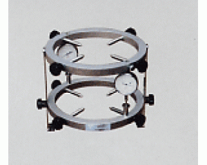
Product Name: TM- TM- Type II concrete elastic modulus measuring instrument, round, concrete elastic modulus measuring instrument , Elastic Modulus Concrete Elastic Modulus Tester This device is primarily used to determine the static compression modulus of concrete prism or cylinder specimens. It works by measuring the displacement or strain of the specimen under pressure (or tension) when connected to various testing machines. The elastic modulus is then calculated, allowing for an accurate assessment of the mechanical properties and performance of the material under load. It offers several advantages, including a lightweight design, compact structure, clear readings, and corrosion resistance. As a mechanical measuring instrument commonly used in concrete material testing, it has been widely applied in scientific research, engineering projects, and universities for the measurement and analysis of displacement or strain. Concrete Elastic Modulus Tester Instructions: First, adjust the distance between the two cutting edges according to the size of the test piece. If the test piece size is 100×100, tighten the nut first (number 13), then connect the right connector (number 12) with two 25mm long positioning sleeves (number 14). Change the position (i.e., connect the connecting plate to the inside of the two positioning sleeves), and then tighten the tightening nut. If the test piece size is 125×125, loosen the fastening nut, place the right connection on the two 25mm positioning sleeves, align them in the middle, and tighten the retaining nut. If the test piece size is 150×150, place the right connection on the outer edge of the two 25mm positioning sleeves as shown in the structural diagram. On the left and right bases (number 17 and 19), install the left and right rulers (number 2 and 7), and tighten the set screws to fix the scale. Adjust the position of the upper knife edge so that the spacing between the upper and lower knife edges (number 6 and 11) matches the required distance, then tighten the screws (number 5). Mount the two metering tables (number 1 and 8) on the left and right bases respectively, and adjust their positions to ensure proper contact. Hold the left and right connecting plates (number 16 and 12) with both hands and evenly compress the position. If the spring clamping force is insufficient, turn the adjusting nut (number 21) to adjust the spring pressure. When measuring compression deformation, after clamping the test piece (number 9), spin the fixing screw down to the bottom of the lower knife edge, approximately 7mm. After the test, reset it so that the bottom of the lower blade is horizontal. When measuring tensile deformation, there is no need to rotate the positioning screw down; keep the bottom surface of the lower blade in a horizontal position. To enhance the clamping force of the upper knife edge, you can also use the hand wheel (number 4) for adjustment. The compression amount of the test piece within the gauge length range is determined by taking the average of the two table values. ----------------
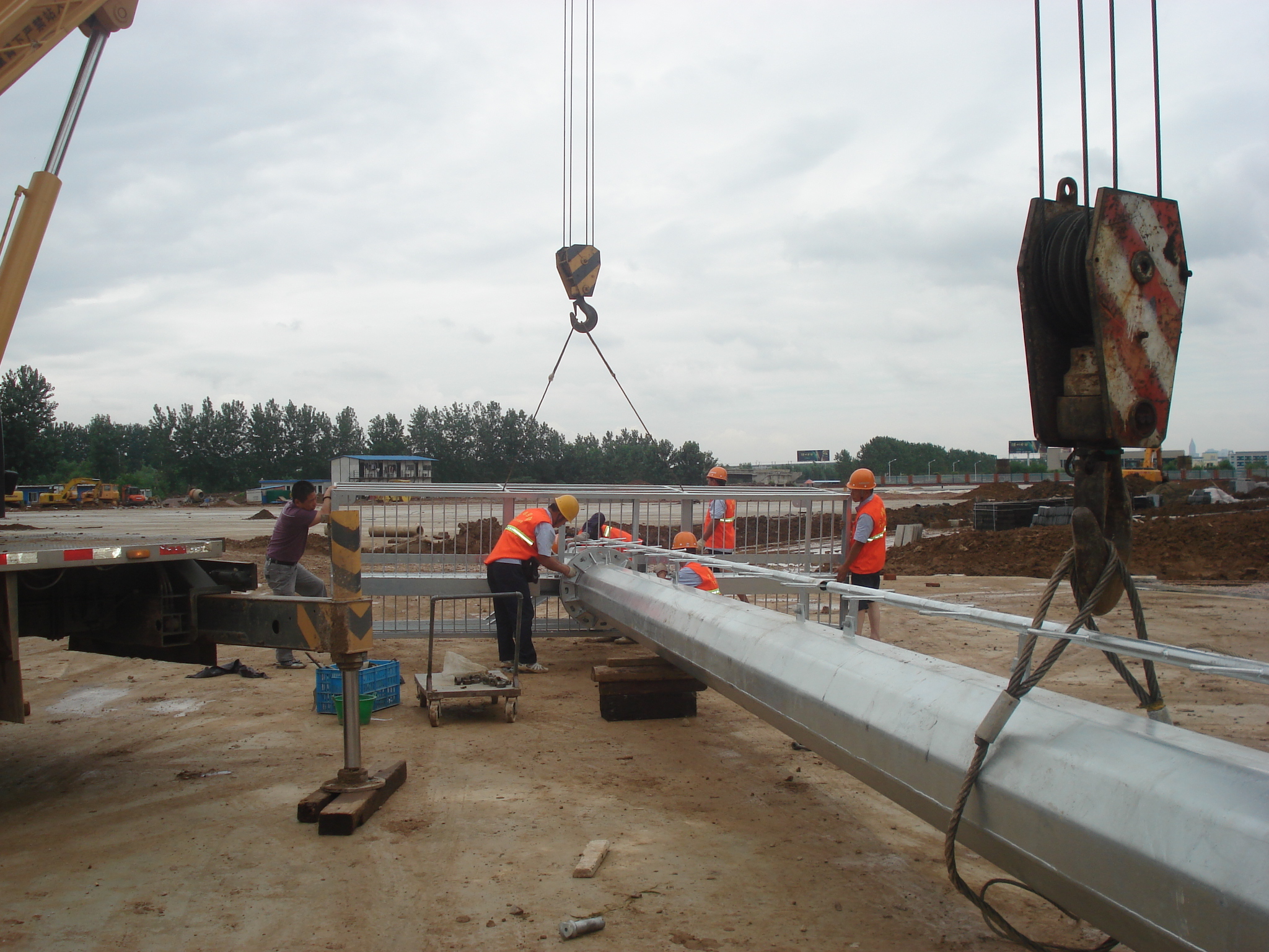
In order to meet the individual requirements of the clients, we offer an extensive range of tubular steel poles and tubular poles that are acclaimed among the clients for durable standards and exceptional finishing. We offer them in standard sizes and durable in nature. Steel Tubular Poles are corrosion resistant in nature and is delivered in well-defined time frame.
1.Shape:Conoid ,Multi-pyramidal,Columniform,polygonal or conical
2.Material:steel plate.stainless steel compound plate,stainless steel plate,ect.(anticorrosion treatment with hot galvanization,also color polyester power could be coated on the surface)
High strength low alloy steel Q235,Q345,GR65,GR50 to ensure the mechanical properity of microelement in order to ensure the quality of galvanization (other materials are also avaliable on request)
3.Jointing of pole with insert mode,innerflange mode,face to face joint mode
4.Design of pole :against earthquake of 8 grade ,aganist wind pressure of 160
5.Minimum yield strength:355 mpa
6.Minimum ultimate tensile strength :490 mpa
7.Max ultimate tensilestrength:620 mpa
8.Certificate:ISO9001-2000
9.Length:Within 14m once forming without slip joint
10.Welding:It has past flaw testing.Internal and external double welding makes the welding beautiful in shape
11:Packages:Our poles as normal cover by Mat or straw bale at the top and bottom ,anyway also can following by client required , each 40HC or OT can loading how many pcs will calculation base on the client actually specification and data
Our lighting equipment are made from quality sheet from bending,forming,automatic welding and hot galvanization.We can reach one-run machining length of 14m,and can bend sheet thickness up to 25mm.We adopt advanced welding procedures ,automatically weld main joints and reach rank-II welding quality.
Steel Tubular Pole,Galvanized Tubular Steel,Steel Tubular Pole Tower JIANGSU XINJINLEI STEEL INDUSTRY CO.,LTD , https://www.chinasteelpole.com
1
2
3
4
5
6
7
8
