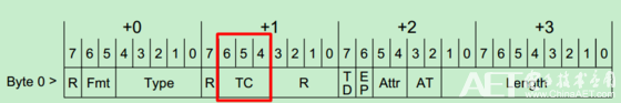
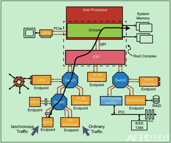
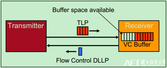
At the beginning of the PCIe bus design, it was mainly aimed at such time-critical applications as audio and video transmission. In order to ensure that these special application data packets can be sent preferentially, PCIe Spec assigns a priority to each packet, which passes through 3 bits in the TLP Header (ie, TC, Traffic Class). As shown below: The larger the TC value, the higher the priority and the corresponding packet will be sent first. In general, a PCIe bus system supporting QoS (Quality of Service) will have an independent Virtual Channel (VC) corresponding to each TC value. This Virtual Channel is actually a Buffer for caching packets. Note: Of course there are also those with only one VC Buffer, regardless of the TC value of the packet, they can only be buffered in the same VC Buffer. Naturally, there is no way to ensure that the priority is transmitted. Such a PCIe device is referred to as a PCIe device that does not support QoS. A simple QoS example is shown below: The lower left corner Endpoint (ie, Isochronous Traffic) has a higher priority than the right Endpoint (ie, Ordinary Traffic). Therefore, in the Switch, packets from the left Endpoint will be transmitted first. This kind of decision operation of Switch is called Port Arbitration. By default, packets in the VC Buffer are placed in the VC Buffer in order of time in which they were reached. However, this is not always the case. The PCIe bus inherits the PCI/PCI-X bus architecture for Transaction-Ordering and Relaxed-Ordering, but it is only valid for the same TC value. About Transaction-Ordering and Relaxed-Ordering, we can refer to PCI-X Spec, which is not described in detail here. For most serial transmission protocols, the premise that the sender can effectively send data to the receiver is that the receiver has enough receive buffers to receive data. In the PCI bus, the sender does not know whether the receiving method has enough buffers to receive data (that is, the receiver is ready) before sending, so it often needs some operation of Disconnects and Retries, which will seriously affect the bus. Transmission efficiency (performance). In order to solve this problem, the PCIe bus proposes the concept of Flow Control as shown in the figure below. The PCIe bus requires that the receiver must always (at specific times) report to the sender about the use of its VC Buffer. The reporting method is that the receiver sends the DLLP (Data Link Layer Packet) of the Flow Control to the sender, and the sending and receiving of this DLLP is done automatically by the hardware and does not require human intervention. It should be noted that although this operation is intended to occur between data link layers, the use of these VC Buffers is also visible to the application layer (software layer). The PCIe bus using the Flow Control mechanism achieves higher bus utilization than the PCI bus. Although Flow Control DLLPs have been added, these DLLPs have very little bandwidth and have little effect on bus utilization.
Any QI enabled device like iPhone X/ 8/8Plus, Galaxy, Samsung S7,S7 Edge, S6,S6 Edge, Nexus 4/5/6 (NOTE: Other device have no wireless charging function except putting on extra receivers.)
Starts the moment you place down any Qi-enabled device or device equipped with a Qi-compatible cover. No cables or USB interface required. Input: AT LEAST 5V/2A; Output: 5V/1A Wireless Charger,Universal Wireless Charger,Portable Wireless Charger,Mobile Wireless Charger Shenzhen Waweis Technology Co., Ltd. , https://www.huaweishiadapter.com