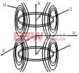
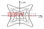
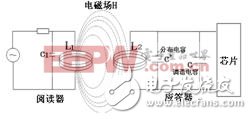
RFID is mainly composed of two parts: a reader and a transponder. The reader (Figure 1) is a data capture system that contains a coupling element that cooperates with the transponder. The transponder (Fig. 2) is a data carrier containing a coupling element composed of a microchip and an antenna coil [1]. Figure 1 reader Figure 2 transponder Figure 3 shows the working principle of the LC oscillator circuit for passive RFID readers and transponders [2]. The reader has an LC tank circuit 1 composed of a capacitor L1 of capacitor L1, which can generate an alternating magnetic field of frequency f0. The distributed capacitance C' of the coil loop in the transponder and the external tuning capacitor C together form a capacitor C2 in parallel with the coil L2 to form an LC tank circuit 2 having a resonant frequency of f, when the transponder coil is placed in the alternating magnetic field of the reader and When the resonance frequency f is the same as the frequency f0 of the alternating magnetic field of the reader, the oscillation circuits 1, 2 resonate. The resonance causes the reader antenna coil to generate a very large current, so that the induced voltage on the transponder coil reaches a maximum value, and is rectified by the diode to provide a stable voltage to the microchip to provide the energy required for the work, and complete the information on the reader to the chip. Read and write [3-4]. Figure 3 How the LC tank circuit of a passive RFID reader and transponder works The frequency of the LC oscillation loop can be calculated according to the Thomson formula (1): The resonant frequency f of the transponder is obtained from the capacitance value C2 and the inductance value L2 of the fabricated LC tank circuit. The antenna coil of the transponder can be produced by various methods such as metal etching, wire winding, vacuum metal plating, and conductive ink printing. After the coil is produced, its inductance value L2 has been determined. According to the measured coil inductance value L2 and the transmission frequency f0 of the reader, the capacitance value C which is required to be matched can be determined. Since the coil circuit is accompanied by a distributed capacitor C', also called internal parasitic capacitance, and the value of the distributed capacitor C' is unmeasurable, it is very important to select the tuning capacitor C by a correct and reasonable method. As shown in Figure 4, the transponder coil printed by the author with conductive ink, according to the reader's transmission frequency requirements, the resonant frequency f of the transponder should be 8.2. The approximate value of the coil inductance measured by the inductance tester is 4.5. Transform formula 1 to get: A capacitor of 82 PF is selected among the standard capacitance values ​​to be applied to both ends of the coil wire shown in FIG. 4, as shown in FIG. 5 for the transponder of the 82PF capacitor. Figure 4 Transponder coil printed with conductive ink Figure 5 Transponder with 85PF appliance Since the distributed capacitance C' of the coil is not taken into account in the calculation, the 82PF capacitance value calculated according to the formula (3) is actually the sum of the distributed capacitance C' and the tuning capacitance C in the transponder. If the 82PF is matched to the coil as the tuning capacitor value, the total capacitance of the coil increases. The resulting resonant frequency in the LC loop must be less than the required 8.2 and will not resonate with the reader. Therefore, the tuning capacitor must be corrected. value. In the process of correcting the tuning capacitor value, it is necessary to repeatedly detect the resonant frequency of the electronic tag after correction, which requires a special instrument to measure the resonant frequency of the electronic tag, since there is no resonance frequency for detecting the passive electronic tag. The right instrument, so I designed a coupler, this coupler can do a good job of detecting the resonant frequency of the electronic tag through experiments. Let's take a closer look at this coupler. The core part of the coupler is two sets of coils 2 and 3 with a radius r and a number of turns N around the hollow cylinder. The two sets of coils are parallel coaxial, and the center distance L is exactly the coil radius r, thus forming a Helmholtz coil [5-6]. As shown in Figure 6. Figure 6 Schematic diagram of Helmholtz coil structure Take the center "O" of L as the center of the x, y, and z axes of the space coordinate system. The resulting magnetic field distribution is shown in Figure 7. Figure 7 Helmholtz coil magnetic field uniform distribution curve The relative errors of the magnetic induction H of each point in the curves "I", "II", and "II" in Fig. 7 and the magnetic induction intensity H0 at the center point are less than 1.0%, 0.1%, and 0.01%, respectively, and the magnetic field near the center point 0 is fairly uniform. The closer to the center point, the better the magnetic field uniformity. Therefore, when detecting the frequency of the passive RFID transponder, the transponder is placed at the center point O of the magnetic field space generated by the Helmholtz coil, so that the magnetic field obtained at each point on the transponder plane is uniform, and the magnetic induction is almost equal. . Shaded Pole Motor,Capacitor Motor Yc Series,Capacitor Motor Tl61,Shaded Pole Ac Motor Wentelon Micro-Motor Co.,Ltd. , https://www.wentelon.com

![]() (1)
(1) ![]() (2)
(2) ![]() (3)
(3)