Abstract: In order to transmit multiple video digital signals in a CPU with limited interface, a video synthesis method is introduced, which uses 4 channels of BT through FPGA. 656 standard D1 format video signal is synthesized into 1 channel BT. 656 D1 format video signal. The video signal after A/D conversion is the digital video signal of the standard D1 format. The FPGA generates the read/write signal to control the dual-port RAM read and write operation. The digital video signal of the D1 format is first stored in the dual-port RAM, and then read in a time-sharing manner. 4 RAM, reduce each digital video signal in D1 format to digital video signal in CIF format, and generate 1 new BT. 656 standard D1 format video signal. Practice has proved that this method can effectively complete video synthesis and meet design requirements. This article refers to the address: http://
We disign and manufacture Linear Actuators For Smart Furniture, modern furniture, like: shelves, bookshelves, shelving, chairs, tables, and desks for the office.
Pls feel free to contact us for more details about this product or other optional product or customize your product!
Linear Electric Actuator is a comfortable and ergonomically correct Actuator, It can provide perfect control and reliable performance to lift, push, tilt or adjust saftly, smoothly and accurately, this Electric Actuator is widely used for various applications, Linear Actuator designed specialized for Smart office furniture , household furniture and medical equipment, such as adjustable work table, electric beauty bed, massage chairs, TV lift, taction beds, dental bed, hospital bed, dental chairs, electric wheel chairs, leisure bed, Smart Recliner chairs, etc...
Electric Linear Actuators for Smart Office, Electric Actuators for Smart Office, Linear Actuators for Smart Office TOMUU (DONGGUAN) ACTUATOR TECHNOLOGY CO., LTD. , http://www.tomuu.com
Keywords: video synthesis; BT. 656; FPGA; digital video
In many video applications, multiple digital video signals are required. Some video microprocessors have limited input and output interfaces and cannot transmit multiple digital video signals. Therefore, it is very meaningful to synthesize and transmit video signals. The common practice is to synthesize through programmable logic devices. In view of this, this paper uses ITU-RBT. 656 unique frame structure, discussed the four-way ITU-R BT. 656 digital video signals are synthesized into one channel ITU-R BT. 656 digital video signal method.
1 system design
1.1 Hardware Framework This design implements 4-way ITU-R BT through FPGA. The 656 D1 format digital video signal is transmitted in one video channel. The coupling synthesis logic is added between the output of the video decoder (SAA7113) and the video input port of the CPU, and the coupling between the two is realized by the FPGA. The hardware connection diagram is shown in Figure 1. The FPGA and SAA7113 are coupled through dual-port RAM. The FPGA controls the read/write logic of the dual-port RAM, and reads the data in the four dual-port RAMs in a time-sharing manner. The digital video signals are synthesized in the FPGA. . 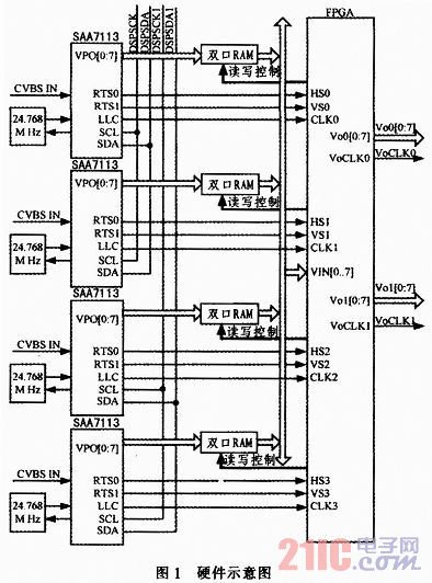
The SAA7113 external clock source is provided by a 24.768 M crystal. The internal PLL generates the operating clock required by the SAA7113. The VPO output clock frequency is 27 MHz. The initialization of the SAA7113 is done by the CPU through two sets of I2C buses, and each of the two SAA7113s uses a different I2C slave address (by setting RTS0). Four analog CVBS signals are input into four SAA7113 AI22.4 SAA7113 VPO buses are respectively connected to the input of four dual-port RAM, SAS7113 RTS0, RTS1, LLC are connected to the FPGA, and the FPGA controls the dual port according to the video synchronization information. The read and write timing of the RAM, the data output of the dual port RAM is connected to the FPGA in the form of a bus.
1.2 Main device selection The system uses SAA7113 as an A/D converter. SAA7113 is a video decoding chip. It can select 4 analog input video signals by configuring internal registers. The input signals can be 4 CVBS or 2 S video (Y/C) signals, and output 8-bit bus. ITU-R BT. 656 YUV 4:2:2 format video stream, can be configured in 10-bit mode. The 7113 supports multiple modes of PAL, NTSC, and SECAM. It can automatically convert between PAL and NTSC and automatically detect the field frequency (50 Hz or 60 Hz). The control of chromaticity, brightness, etc. is realized by writing different configuration values ​​to the corresponding registers, and the reading and writing of the registers is performed through the I2C bus.
This design uses the SAA7113 LLC clock output clock signal 27 MHz as the FPGA input clock source, which is multiplied by the on-chip PLL, used as the FPGA global clock, and reset using the power-on reset.
The FPGA uses Xilinx's high-capacity, low-cost, low-power Spartan-3E series XC3S250E. The advantages of the Spartan-3E family are primarily the protocols required for system connectivity (including physical parallel I/O interfaces) and high bandwidth. The Spartan-3E device I/O pins support all SelectIO. Supports 18 general purpose I/O interface standards (PCI 64/66, PCI-X 100, RSDS and mini-LVDS, etc.), as well as common DDR memory interfaces. Provides up to 9.1 billion multiply-accumulate (MAC) per second. A built-in 18x18 embedded multiplier can be used to implement tight DSP architectures (such as MAC engines and adaptive, fully parallel FIR filters). The SRL16 shift register logic and distributed memory can be used to implement high density DSP structures such as filters. The core voltage is 12V and 2.5V, and the IO voltage is 3.3V. The XC3S250E provides 250,000 equivalent logic gates. This product is available in a PQ208 package and provides 158 user-available input/output pins.
In this design, the XC3S250E is configured in Slave Serial mode (M[2:0] = "111"), and the FPGA configuration data is written to the FPGA through the synchronous serial interface through the CPU. The CPU uses the GPIO pins to simulate the serial configuration timing of the FPGA.
In order to facilitate the debugging of the FPGA, a JTAG configuration interface is reserved on the circuit board.
This design requires four channels of 720x576 video data to be stored. Each channel has 576 rows x 720x2 bytes (in a 4:2:2 YCbCr signal, one dot actually occupies 2 bytes (indicated by luminance chromatic aberration)). Therefore, each channel requires about 800 kB of storage space. Four 1 MB dual-port SRAMs are used in the design to buffer 4 channels of video data.
For the FPGA module, the input 5.0 V is converted to 3.3V by one TPS76833 for use by the FPGA VCCO. 5.0V is converted to a voltage of +2.6V/2A after one RT8011 conversion, and is provided to the VCCAUX of XC3S250E. Another route RT9183 LDO is converted to +1.2V/1.5A voltage to supply power to the XC3S250E core. The input 5.0V is converted to 3.3V via a TPS76833 to power other devices.
2 Video synthesis description This article describes the specific implementation of video synthesis for the PAL system: 4 channels of data are reduced by 1/2 in the horizontal/vertical direction respectively (reduced from D1 format to CIF format): 4 CIF format numbers The video stream is spliced ​​into one ITU-R BT. 656 digital video stream, connected to the video port of the CPU (DSP). Through the synthesis of the input data of the four channels of SAA7113 through the FPGA, four 352x288 pixel video signals can be simultaneously transmitted.
After the analog CVBS signal is input, after the relevant processing (clamping, amplitude amplification, anti-aliasing filtering, A/D conversion, YUV separation) circuit, it is converted to BT. The 656 D frequency data stream, the video data source output from the SAA7113 is a video source with a resolution of 720x576 D1 format. The resolution is 720x576, 625 lines per frame, 1728 pixels per line. It can be divided into 4 channels of 252x288 pixels, and the extra space is filled by data 8010.
First configure the SAA7113 related registers, configure RTS0 and RTS1 as HS and VS. The FPGA uses the on-chip counter to perform frame synchronization detection on the BT656 data stream according to the timing relationship between HS and VS, find accurate synchronization information, and determine timing information. Then start the dual-port RAM write operation (the write RAM address strictly corresponds to the line timing of the BT656, agree on a mapping relationship to facilitate the read operation), and then control the dual-port RAM read timing according to the timing information, and read the 4-channel dual-port RAM. The data lines of the terminals are connected in a bus manner, and the FPGA reads the different RAM modules in a time-sharing manner. The data of 4 RAMs to the FPGA is continuous. They are time-divisionally from different modules and are filled into the corresponding areas. The original data storage location is used to store the first and second video sources. The location of the two fields of data is used to store the 3rd and 4th video sources, and the ITU-R BT is inserted at the same time. 656 frame format synchronization information, other locations inserted fixed data 8010, resulting in one way to comply with ITU-R BT. 656 standard digital video stream in D1 format.
After the synthesis process, the FPGA can provide one channel for the CPU to comply with ITU-R BT. 656 D1 format video data stream.
3 Experimental analysis and conclusions The system performance was tested thoroughly, and the input composite video data was tested by video encoder. In order to test the design to meet the predetermined requirements, a variety of video input sources have been selected for testing, such as testing the speed and severity of the motion, black and white for testing black and white images, and step patterns for testing brightness levels.
The experimental results show that when the 4-channel D1 image is input, the average signal-to-noise ratio is more than 33 dB, which can be encoded in real time. The decoded image is clear and smooth, without mosaic and animation, with bright colors and clear brightness.
This paper discusses a method of synthesizing one channel D1 format video stream by four D1 video streams. This design can fully meet the multi-channel video data transmission under certain conditions, which meets the practical application scenarios and meets the design requirements.