1 Introduction At present, most of the rice cookers on the market are heated by mechanical means or by fixed power. The energy utilization rate is low and the function is single, which is difficult to meet the growing needs of people. Therefore, it is very necessary to develop a fully functional, safe and reliable microcomputer rice cooker. From the mechanical principle to the current smart rice cooker, the rice cooker has gone through many stages. The rice cooker plays a high-tech advantage and is dominated by delicious cooking, which makes the products more abundant and fashionable. It has formed three types of microcomputers, computers and machinery, and ten different styles. Although the mechanical rice cooker reflects its superiority in terms of price, it is difficult to meet the high quality demand of modern life in other aspects. The microcomputer or computer-controlled smart rice cooker meets the requirements of modern people. The user-friendly interface design allows people to see the current working status at a glance, giving you more peace of mind. All cooking processes are automatically controlled by the computer, and most of the smart rice cookers use space. "Black crystal" liner, super hard wearable, long-lasting beauty, all these characteristics are in line with modern people's concept of saving time, effort and durability. This article refers to the address: http:// The SIMATIC S7-300 universal Controllers saves on installation space and features a modular design. A wide range of modules can be used to expand the system centrally or to create decentralized structures according to the task at hand, and facilitates a cost-effective stock of spare parts. SIMATIC is known for continuity and quality. Simatic S7 Plc,Simatic S7 400 Plc,Siemens Simatic S7,Programmable Logic Controller Simatic S7 Xiamen The Anaswers Trade Co,.LTD , http://www.answersplc.com
This article mainly introduces the SPMC65P2404A chip to control the process of rice cooker. SPMC65P2404A is the 8-bit single-chip microcomputer of Lingyang Company. The highest working frequency is 8MHz, the working voltage is 2.5V~5V, there are 192 bytes of RAM and 4K bytes. OTP ROM, 23 programmable IO ports, 8 channels 10-bit A/D converter, 2 channels 8-bit timer/counter, 2 channels 16-bit timer/counter, 1 12-bit PWM output port, low voltage, upper The power, watchdog, external signal, error address reset, and a beep output.
2 The overall scheme introduces the block diagram of the intelligent rice cooker control system designed by using the Lingyang 8-bit MCU. As shown in Figure 2-1, the function mode is selected by pressing the button, the display circuit is completed to display the current state and the timing time; the temperature is used to measure the temperature. Sampling is performed; the control of the relay is finally realized by the control of the MCU, thereby controlling the heating of the heating plate, and the power supply part completes supplying 5V power to the single-chip microcomputer system and the peripheral circuit, and heating the heating plate. 
3 system hardware design
1. The hardware schematic diagram of the rice cooker controlled by the single-chip SPMC65P2404A is shown in Figure 3-1. It includes the button input part, the temperature detection input circuit, the reset and the crystal oscillator circuit, and the PA6 and PA7 complete the temperature of the top cover and the chassis. Detection, PA5 completes the control of the relay, SPMC65P2404A is the core part of the system. 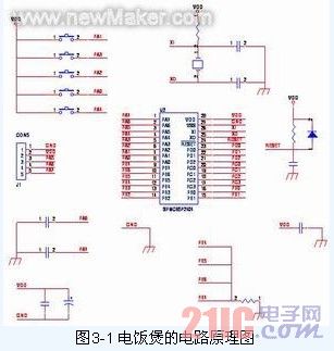
Chip characteristics
SPMC65P2404A is an 8-bit single-chip microcomputer of Lingyang Company. The maximum working frequency is 8MHz, the working voltage is 2.5V~5V, there are 192 bytes of RAM and 4K bytes of OTP ROM, there are 23 programmable IO ports, 8 channels and 10 bits. A/D converter, 2-channel 8-bit timer/counter, 2-channel 16-bit timer/counter, 1 12-bit PWM output port, low voltage, power-on, watchdog, external signal, error address reset, and A bee caller output... With these resources, the function of the rice cooker can be realized.
2, the display circuit:
The display circuit consists of a common anode digital tube and 10 LEDs. The display status of the corresponding LED and digital tube is illuminated by the selection of the microcontroller and the data sent. The schematic diagram of the circuit is shown in Figure 3-2: 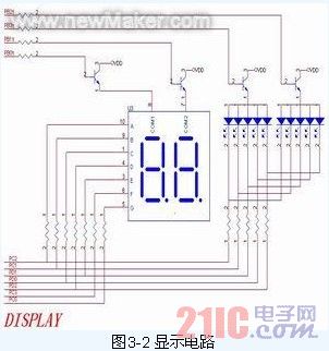
3, power circuit:
The power supply part provides a +5V DC voltage regulator for the MCU, and supplies power to the relay through the voltage of +14V after buck, rectification and filtering, and controls the working state of the relay by controlling the conduction of the emitter of the triode. The schematic diagram of the power circuit is shown in Figure 3-3: 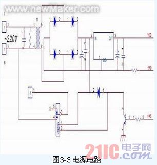
4, the temperature acquisition part of the circuit diagram:
J2 and J3 are the two interfaces of the temperature sensor, wherein J2 and J3 are the interfaces of the top cover and the chassis temperature sensor respectively. The signal detected by the single chip is actually the voltage value of the resistor divided by the temperature sensor, due to the resistance value of the temperature sensor. It will decrease with the rise of temperature, so the voltage value of the voltage divider resistor indirectly reflects the temperature at a certain moment. The circuit schematic is shown in Figure 3-4: 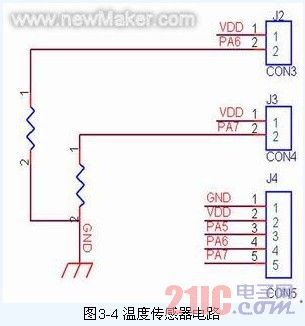
4 system software design
4.1 Main program flow The whole system is roughly designed from the prototype analysis. The whole system input includes 2 temperature sensors and 5 buttons. The output includes 2 7-segment digital tubes, 10 LEDs, relay control signals and so on. According to the control function, the program is designed into several main modules. The main flow of the program is shown in Figure 4-1: 
4.2 Introduction to subroutines
1. Diagnostic subroutine Diagnostic program mainly performs temperature collection and determines whether the sensor is good. It mainly tests 20 temperature sensors continuously for 20 times. If the measured data is out of range (temperature range: -10 °C~160 °C), it indicates If the sensor is short-circuited or open-circuited, the digital display “E†and the button operation is prohibited.
2. The keyboard scanning subroutine program scans the keyboard once every cycle. If the key is pressed after scanning, the key value is temporarily stored. If the key values ​​scanned for 5 consecutive times are the same, it is considered to be a stable key value.
3, the system has a total of 5 buttons, in different states, each button is only one tap, the effective system's five keys are connected to PA1, PA3, PA2, PA0, PA4, if the button value is valid, the corresponding value of the return value Is 0, otherwise the corresponding bit is 1.
4. Temperature collection subroutine The thermistor has high sensitivity. In order to prevent interference and other reasons, the measured temperature value changes too fast, causing frequent control of the control components. The temperature acquisition adopts the sliding uniform value filtering method. That is, three data are continuously collected on the same channel, and the intermediate value is taken.
5. The display subroutine system has 2 7-segment digital tube display and 10 LED display. There are six main types of digital tubes to display: standby status, error display, risotto, heat preservation, cooking and timing display. The LEDs show the selected function, start and hold status. The function display needs to adopt the round robin mode, and the start light flashes before the start button is pressed. After entering the insulation state, the heat preservation indicator lights up. The LED display program consists of a bit code scanning subroutine and a digital display status selection subroutine.