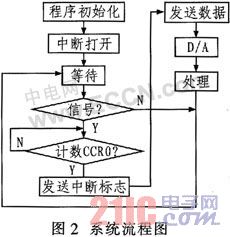
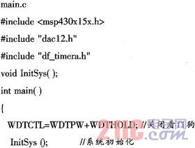
3.1 The main peripheral circuit inside the microcontroller This article refers to the address: http:// Crystal Oscillator Circuit: The most sensitive ones are the clock signal, reset signal and interrupt signal. If electromagnetic interference intrudes into these signals, it is most likely to disturb the microcontroller and cause the system to malfunction. Especially after accumulating noise interference in the clock signal. Will change the clock frequency division signal, resulting in disorder of the working sequence of the microcontroller. The system provides high-speed and low-speed crystal oscillator circuits, which can output different frequency clocks in different modules of the microcontroller. Users can use the high-speed crystal oscillator to generate the higher frequency MCLK to supply the CPU to meet the high-speed data operation needs. It can also turn off the high-speed crystal oscillator when the CPU is not needed, and the low-speed crystal oscillator can be used for the real-time clock. ACLK. Input, output, power supply and other circuits should be connected in parallel with some small capacitors to avoid noise interference. 12-bit D/A converter module: Compared with the earlier models, the MSP430F15/16x series MCUs have added dual 12-bit D/A converters. The D/A converter is mainly used to convert the digital output of the MCU. For the actual analog quantity to control the external device. This D/A converter can be set to 8-bit or 12-bit conversion mode during use. Ideally, the resolution is 1/256 when 8-bit conversion mode is selected and 1/4 096 when 12-bit is selected. The D/A converter completes the output of the control signal with the cooperation of the timer Timer_A. Timer Timer_A Module: The timer of the MSP430F157 microcontroller is a 16-bit counter with four operating modes: stop mode, up counting mode, continuous counting mode, and up/down counting mode. One of four modes can be selected by setting the corresponding Timer A register. Moreover, Timer_A has two interrupt vectors, namely CCR0 interrupt vector and TAIV interrupt vector, where CCR0 is a single source interrupt vector with the highest priority; TAIV is a multi-source interrupt vector with lower priority. In this system, select the up counting mode, use CCR0 to set the interrupt frequency of the timer, and control the sampling time. Control principle: When the resonant cavity changes from the detuned state to the resonant state, the output power drops to zero, and the output detunes zero signal. At this time, a falling edge from "1" to "0" is obtained, so that the Timer_A of the single chip microcomputer Stop counting, the output remains unchanged until the humidity changes, the resonant cavity from the resonant state to the detuned state, producing a rising edge of "0" to "1", at which time Timer_A starts counting. When counting to CCR0, the interrupt flag is sent and D/A conversion is started. If you get a new data set a flag to inform the main program, then wait for the next signal to arrive. 3.2 Device Selection The operating voltage of the MSP430F157 is 3.3 V. The existing switching power supply cannot be provided. In addition, considering the system requirements, the power supply has the functions of voltage regulation, small ripple, and low power consumption of the hardware system. Therefore, the power supply part adopts TI. TPS76033 or LM1117. Both devices are well suited to hardware system requirements and, in addition, have a small package. Can effectively save PCB area. In the single-chip microcomputer system, the single-chip microcomputer needs a reset circuit, and the reset circuit can adopt an RC circuit or a reset device. The RC reset circuit is low in cost but not highly reliable; the reset device has high reliability. In order to ensure the reliability of the reset circuit, the system uses the reset device MAX809STR to implement the reset circuit. The temperature measurement circuit is implemented by the XTR101 device. The XTR101 is a precision, low drift, two-wire transmitter that amplifies and converts weak voltage signals into 4 mA to 20 mA current signals for long distance transmission. It consists of a precision 1 mA current source with an offset voltage of 30μV, a temperature drift of 0.75μV/°C, and a nonlinearity of 0.01%.      Frequency measurement circuit: In order to simplify the circuit and improve the integration degree, the system frequency measurement part is realized by CPLD. 4 software design      The code memory space of MSP430 series MCU ranges from 1 kB to 60 kB. When the amount of programs is greater than 8 kB, the use of assembly language can greatly reduce the efficiency of software design work. Using C language to achieve system application software development can greatly improve the efficiency of development and debugging; at the same time, the generated documentation is easy to understand and easy to transplant. The C language for the MSP430 series is compatible with the standard C language. The integrated debugging environment IAR Embedded Workbench and C language C-SPY debugger provided by American IAR company are selected as the development platform. It is a flexible and convenient integrated environment for developing different target processor applications, providing a user-friendly interface and a powerful debugging environment for developing applications for the MSP430 family of microcontrollers. MSP430 series MCUs can be directly downloaded to the on-chip Flash memory for offline operation using Workbench. During the debugging process, you can see the contents of each register in the upper layer software and modify it online, support single-step operation, and you can observe the real-time values ​​of each variable defined online. By organizing all relevant files into a project, the compile runtime software automatically combines the files intrinsically linked to support C programming. The system software design flow is shown in Figure 2.   The main program of the system is: 5 Conclusion      Compared with the control system realized by the separate components in the past, the humidity measurement control system realized by the MSP430F157 single-chip microcomputer introduced in this paper has high precision, simple design and less wiring, avoiding electromagnetic interference and short circuit phenomenon due to the close proximity between the wires. The software design uses IAR Embedded Workbench and C language C-SPY debugger as the development platform, which is powerful and easy to operate.
Mini Fan with 3 modes: first-fan mode, second-misty mode, third-fan+misty, always keep your skin fresh
Functional Misting Fan: USB mini cooling fan and beauty Humidifier 2 in 1, hand misty fan for lasting your makeup or cooling after exercise
Convenient personal fan: operated by built-in rechargeable battery or a micro USB cable(included in the package)
Light portable fan, light-weight and handle design , convenient to carry anywhere and anytime
Two switch to operate: use "on/ off" switch to turn on and off the device; "control key" button is to choose the circulation modes you like
Rechargeable Mini Fan,Portable Rechargeable Fan,Rechargeable Fan,Rechargeable Table Fan Shenzhen Hygea Technology Co.,Ltd , http://www.hygeaaromadiffuser.com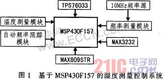
![]()
")
Research on Steam Humidity Measurement and Control System in Steam Turbine
1 Introduction
With the continuous advancement of industrial technology, the steam turbine unit is developing in the direction of high-power nuclear energy. The last stage of the high-power steam turbine of the thermal power plant and all the stages of the nuclear power plant work in the wet steam state. The steam engine has an important influence on the working efficiency of the steam turbine and the safety of the blade.
Therefore, measuring the humidity of the flowing wet steam in the steam turbine and controlling the humidity is of great significance for ensuring the economical, efficient, safe and reliable operation of the steam turbine. This paper introduces a steam humidity measurement and control system using a microwave resonator as a humidity sensor and a MSP430F157 microcontroller as a controller.
The MSP430 series MCU is an ultra-low-power Flash 16-bit reduced instruction MCU introduced by Texas Instruments. It has a very high integration. Its main features are: processor power consumption (1.8 V to 3.6 V, 0.1 μA to 400 μA, 250 μA/ MIPS) and line output leakage current (maximum 50 nA), far lower than other series, the traditional MCS51 microcontroller consumes 10 mA to 20 mA in active mode. Vector interrupts support more than 10 interrupt sources and can be nested arbitrarily. The execution speed is fast, one instruction can be executed in one clock cycle, and the traditional MCS51 microcontroller needs 12 clock cycles to execute an instruction.
2 Working principle
The humidity measurement system consists of microwave signal source, directional coupler, circulator, resonator, detector and other microwave devices as well as DC amplifier, frequency measurement system, digital signal processing system and other circuits.
When the system works, the resonant frequency of the microwave resonant cavity will have a frequency offset with the humidity of the flowing steam. Once the resonant frequency of the resonant cavity changes, the frequency scanning tracking loop will lose lock and the detector will detect the loss of lock in time. The signal is amplified by a DC amplifier and sent to a frequency tracking system to obtain a control signal that controls the VCO to generate a series of scan signals to scan the stabilized resonant frequency until the resonant frequency is scanned and locked. The signal generated by the VCO is coupled to the frequency converter via a directional coupler in the frequency measurement loop. The signal obtained by mixing the signal with the local oscillator signal is amplified by the intermediate frequency amplifier and then output an intermediate frequency signal, which is sent to the frequency measurement system for frequency. measuring. The measured intermediate frequency is then converted by the data processing system to obtain the resonant frequency and frequency offset. The resonant frequency will be transmitted to the microcontroller for data processing along with the steam humidity and pressure to obtain the vapor humidity.
3 hardware design
The humidity measurement control system is mainly completed by the MSP430F157 microcontroller. In essence, the work of the MCU control system can be summarized into three steps: real-time data acquisition, real-time data processing, and real-time control output. The hardware circuit design of this system mainly consists of temperature measurement module, frequency tracking module, power supply circuit, reset circuit and frequency measurement module. The MSP430F157 microcontroller contains two clocks of 32.768 kHz and 8 MHz; the internal 12-bit DAC completes the digital-to-analog conversion of the tracking module. The result of the conversion is used to adjust the VCO output voltage to ensure the consistency of the VCO output frequency and the resonant frequency of the resonant cavity. The internal timer Timer_A generates the sampling frequency of the D/A conversion. The humidity measurement control system based on MSP430F157 is shown in Figure 1.