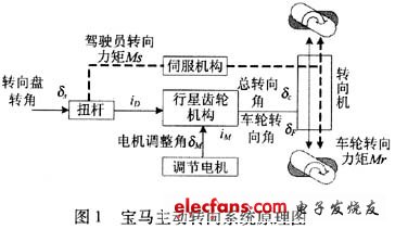
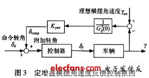
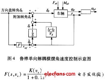
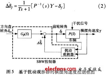
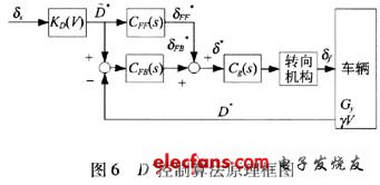
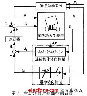
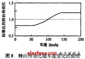
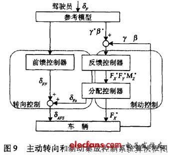
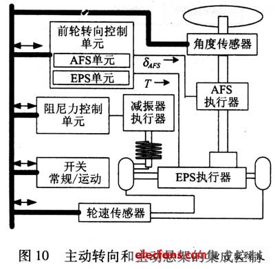
Common active steering systems include active front steering system AFS and four-wheel steering (also known as active rear steering). Active front wheel steering is a technology developed with the development of wire-controlled steering technology, and has entered the practical stage as BMW's active steering system is assembled with real vehicles. Since the active front wheel steering is compatible with the structure of the traditional vehicle, and the improvement effect on the steering stability of the vehicle is obvious, it shows a good development prospect and becomes one of the main directions for the future development of the steering system. This article refers to the address: http:// 1 Working principle of active front wheel steering system The active steering system currently available for passenger cars has two main forms: a mechanical active steering system represented by the AFS system jointly developed by BMW and ZF, which increases the input freedom by the planetary gear mechanical structure. Additional steering, currently equipped in the BMW 5 Series sedan, as well as MANDO in Korea, TRW in the US, JTEKT in Japan have similar products; the other is the wire-controlled steering system (SWB), which uses the controller to integrate driver steering. The angular input and the state of the vehicle at the time determine the output current of the steering motor and ultimately drive the front wheel to rotate. The system has been widely adopted in many concept car and laboratory studies. For example, GM's Sequel fuel cell concept car uses wire-steering technology. The biggest difference between the steer-by-wire and the mechanical active steering system is that when the system fails, the mechanical active steering system can still ensure the steering performance through the mechanical connection between the steering wheel and the wheel, while the steer-by-wire steering must pass through the main parts of the system. Redundant design to ensure the safety of the vehicle. Due to the above safety and reliability reasons, it is currently not legally allowed to directly equip the steer-by-wire system with the vehicle. 1.1 Mechanical Active Steering System The BMW AFS system is taken as an example to introduce the structure and working principle of the mechanical active steering system. The system is mainly composed of three subsystems: hydraulic power steering rack and pinion power steering system, variable transmission ratio execution system and electronic control system. The system schematic is shown in Figure 1. In addition to the traditional steering mechanical components, the system mainly includes two core components: one is a double planetary gear mechanism, which realizes the variable transmission ratio function through superimposed steering; the other is the Sewtronic hydraulic servo steering system, which is used to realize the steering assist function. . During the driving process, the torque and the angle input by the driver are transmitted to the torsion bar together. The torque input is assisted by the hydraulic servo mechanism according to the vehicle speed and the steering angle, and the angular input is driven by the double planetary gear mechanism driven by the servo motor. The additional corners of the controller output are angularly superimposed, and the superimposed total steering angle is the final corner transmitted to the rack and pinion steering mechanism. The rotation angle of the controller is calculated based on the signals of the respective sensors, including the wheel speed, the steering angle, the yaw rate, and the lateral acceleration. Thanks to the BMW Active Steering System, not only the steering torque can be adjusted, but also the steering angle can be adjusted so that the steering input is optimally matched to the current speed. 1.2 Wire-controlled steering system Generally speaking, the steer-by-wire system consists of three main parts: the steering wheel assembly, the steering execution assembly and the main controller (ECU), and an auxiliary system such as a fail-safe system and a power supply. The system structure is shown in Figure 2. The steering wheel assembly includes a steering wheel, a steering wheel angle sensor, a torque sensor, and a steering wheel returning positive torque motor. Its main function is to convert the driver's steering intention (by measuring the steering wheel angle) into a digital signal and transmit it to the main controller; at the same time, accept the torque signal from the main controller to generate the steering wheel return torque to provide to the driver. Corresponding road information. The steering execution assembly includes a front wheel angle sensor, a steering execution motor, a steering motor controller, and a front wheel steering assembly. The function of the steering execution assembly is to accept the command of the main controller and control the steering wheel rotation by the steering motor controller to realize the steering intention of the driver. The main controller analyzes and processes the collected signals, determines the motion state of the car, sends instructions to the steering wheel back to the positive motor and the steering motor, controls the work of the two motors, and ensures an ideal vehicle response under various working conditions. Reduce the driver's compensation task for the steering characteristics of the car as the vehicle speed changes, reducing the burden on the driver. At the same time, the controller can also judge the operation of the driver. Due to the special structure of the steer-by-wire system, the fail-safe system becomes an important module of the steer-by-wire system. It includes a series of monitoring and implementation algorithms to deal with different fault forms and fault levels. Maximize the normal running of the car. 2 Active front wheel steering dynamics control 2.1 Control of yaw rate In a typical driving operation, the driver has to complete two tasks at the same time: (1) path following; (2) maintenance of vehicle attitude. Path following is a complex problem that involves the selection and follow-up of routes, and it is currently not possible to completely replace the driver by the controller. Conversely, because the influence of external disturbances on the vehicle's attitude is often sudden, the control of the vehicle's attitude is more difficult for the driver, especially for the novice. Such control is completely achievable by the controller. Since the dynamic parameters related to the attitude control of the vehicle are mainly the yaw rate, the control of the yaw rate is also the most important aspect of the active front wheel steering control. There are three common methods for controlling the yaw rate: (1) yaw rate feedback control; (2) robust one-way decoupling yaw rate control; and (3) yaw rate control based on disturbance observer. The basic idea of ​​yaw rate feedback control is to use the difference between the ideal yaw rate Yest and the actual yaw rate Y for feedback control. BMW's active steering system uses a yaw rate feedback control method, and its controller is PI controlled. The yaw rate feedback control not only increases the bandwidth of the yaw rate response, but also increases the yaw rate damping, especially when the vehicle speed is high. However, there is also a gain that reduces the yaw rate and the lateral acceleration, which makes the driver difficult to operate at low speeds. In view of the above problems, the yaw rate feedback control in the form of a fixed gain is generally improved, and the control method can keep the vehicle yaw rate gain constant during feedback control. Figure 3 shows a block diagram of a certain gain yaw rate feedback control. Among them, the gain of the vehicle from the front wheel angle to the yaw rate in the case of constant-speed circular motion, Kyaw is the feedback proportional coefficient. The robust one-way decoupling yaw rate control was proposed by Prof. Ackerman of the German Space Agency. On the basis of reasonable decomposition of the driver's operational tasks, the yaw angular velocity and the lateral acceleration are decoupled one-way, and then the horizontal The swing angle is controlled. The so-called one-way decoupling means that the controller has no influence on the lateral acceleration of the decoupling point of the front axle of the vehicle when feedback control is performed on the yaw rate of the vehicle, and can be passed through the side when the driver performs lateral motion control. The acceleration affects the yaw rate indirectly, ensuring that the vehicle can pass the curve smoothly. This is the biggest feature of the algorithm. Because the algorithm itself has certain robustness to vehicle uncertain parameters (such as vehicle mass distribution, vehicle speed, and adhesion coefficient between tire and ground), it is called robust one-way decoupling control. The robust one-way decoupling control also has the problem that the yaw rate damping decreases with the increase of the vehicle speed, and can be solved by the preset yaw rate damping control method. The method is to trade off between the one-way decoupling control and the yaw rate damping, so as to maintain good yaw rate damping characteristics at different vehicle speeds, and maintain the yaw rate of the vehicle model to the nominal model. Decoupling. Figure 4 shows the robust unidirectional decoupling yaw rate control block diagram. In the figure, the actual control is a decay integral, so that the control of the yaw rate only works within 1 s of the disturbance, helping the driver to stabilize the vehicle. After 1 s, the vehicle will be completely under the control of the driver. under. The reference yaw rate value is calculated from equation (1) and is a steady state value related to speed. In recent years, with the development of control technology, a disturbance observer control method that has been used for motor control in the past has been transplanted into vehicle yaw rate control. The basic principle of the control method is shown in FIG. 5. The feedback compensator established by the disturbance observer theory generates a compensation rotation angle according to the actual yaw angular velocity of the vehicle including the disturbance, and is superimposed on the input rotation angle of the vehicle. Achieve control of the yaw rate of the vehicle. The expression of the feedback compensator is as follows: It can be seen from the expression that the so-called disturbance observer is essentially using the inverse dynamics transfer model of the vehicle to calculate the nominal front wheel angle of the vehicle through the actual yaw rate of the vehicle, and then by the actual front wheel angle The difference is obtained by controlling the corner of the yaw disturbance. Since the yaw rate signal will encounter a noise signal during the control process, the general disturbance observer has a low-pass filter. The low-pass filtering link also has the effect of changing the numerator and denominator order of the inverse kinetic model, so that it can be realized in control. The yaw rate control based on the disturbance observer has a simple structure, clear meaning, and strong robustness to external disturbances and system parameter changes. Theoretical and experimental results show that the control structure of the disturbance observer is more suitable for yaw stability control and becomes a direction for the development of future yaw angular velocity control. 2.2 D* control D* control (or comprehensive control of yaw rate and lateral acceleration) is derived from the control strategy of rear wheel steering in four-wheel steering control, which is a comprehensive control of the yaw rate and lateral acceleration of the vehicle. method. In this control, the amount of feedback of the control is no longer only the yaw rate, but a linear combination of the yaw rate and the lateral acceleration, as shown in equation (3). Where: Cy is the lateral acceleration, and VY is the product of the vehicle speed and the yaw rate. The two dimensions are the same. It can be seen from this that D* control is a control method that focuses on lateral motion control. The D* control block diagram is shown in Figure 6, where D* is derived from the ideal vehicle model and the speed factor associated with the vehicle speed and the angle of the driver input. CFF(s) is a feedforward control transfer function. It mainly realizes the vehicle response gain with vehicle speed. CFS(s) is a feedback control link used to generate additional corners. Compared with the yaw rate feedback control, the D* control can further improve the steering response speed of the vehicle, and improve the ability of the vehicle trajectory tracking while suppressing the disturbance, in the case of relatively high lateral motion requirements (eg, low adhesion). The coefficient of the road is double-shifted, and the lateral gust is straight.) The effect is better. 2.3 Roll stability control During the running of the vehicle, high-speed cornering, emergency avoidance and lateral gust disturbances may directly cause the vehicle to roll over. In addition, vehicles with a high center of gravity are also particularly prone to rollover. Also, when the driver makes a wrong estimate of the lateral stability of the vehicle, it also causes the vehicle to roll over. Lateral acceleration is the main factor affecting the lateral stability of the vehicle. Active steering can effectively affect the lateral acceleration of the vehicle to control the roll of the vehicle. Generally, the anti-rollover control of the vehicle adopts a threshold value indicating the state of the vehicle's roll, and when the detected roll state exceeds the threshold value, the anti-rollover control is triggered. The 阙 value may be the lateral acceleration at the center of gravity, the vehicle rollover factor, or the load transfer coefficient. Figure 7 shows a control system diagram based on active steering and brake integrated control. In the figure, only the rollover coefficient is obtained from the wheel width of the vehicle and the lateral acceleration at the center of gravity of the sprung mass. When |R|<1, it means that the vehicle is laterally stable, and when R=±1, it means that the wheel on the left or right side of the vehicle will lift off the ground. The control has two modes. When |R|<0.9, the vehicle runs normally, the control system is in the continuous steering steering control mode, and the additional rotation angle is generated according to the optimization strategy of the roll damping, which can effectively reduce the roll caused by the steering. The external disturbance in the vehicle's roll resonance frequency band is suppressed. When |R|≥0.9, the vehicle is in a dangerous state of roll, and the control system enters the emergency steering control mode. At this time, the additional rotation angle δR=kR(|R|-0.9) can effectively increase the turning radius of the vehicle, and the system performs Certain emergency braking operations further reduce the speed of the vehicle, thus avoiding rollover of the vehicle. In the active steering rollover control, the presence of additional corners affects the ability of the vehicle to travel according to the driver's intention. Therefore, the control strategy should include a control method for the lane keeping ability of the vehicle while driving, such as active braking. Methods. Since the rollover of the vehicle is relatively harmful, such control generally follows the principle that the rollover control takes precedence over the lane following. 2.4 Control of variable steering ratio The steering stability is actually the characteristic of a closed loop system of a person's car. The stability of the steering is ultimately determined by the driver's feeling. Therefore, in the control of the active front steering, how to improve the safety and comfort of the driver's operation. It has become an important factor in improving the stability of system operation. In a conventional car, the gear ratio from the steering wheel to the wheel is a fixed value. At low speeds, when the vehicle suddenly changes lanes due to obstacles such as parking, it is necessary for the driver to manipulate the steering wheel greatly and quickly, which increases the driver's physical burden. Conversely, at high speeds, the smaller steering wheel angle produces greater lateral acceleration due to the increased steering response gain of the vehicle, increasing the driver's mental burden. The variable steering ratio can effectively solve the above problems. In general, the change in steering ratio in variable steering ratio control depends mainly on two factors: vehicle speed and steering wheel angle. As the vehicle speed increases, the steering gear ratio increases, and as the steering wheel angle increases, the steering gear ratio decreases, as shown in FIG. In this way, the driver can be made to turn at a low speed and the steering is stable at a high speed. In the current active front wheel steering control, many control algorithms use the variable steering ratio control as a feedforward link to improve the steering stability of the vehicle together with the feedback link. In the mechanical active steering system, the variable transmission ratio is realized by the angle superposition method, and the input and output relations are as follows: Where: Wsw is the steering wheel input angle, Wring is the driving gear input rotation angle, and α1 and α2 are the scale factors of the superposition of the two. 3 Prospects for active front wheel steering dynamics control Since the vehicle yaw rate and lateral acceleration are coupled by the lateral force of the tire, the use of active steering through the lateral force to improve the steering stability of the vehicle is bound to face an insurmountable contradiction, that is, the lateral acceleration and the yaw rate cannot be simultaneously compared. The ideal optimization state. How to understand the nature of this contradiction and how to achieve the comprehensive improvement of the lateral and yaw motion of the vehicle to further improve the steering stability of the vehicle will be a problem that we need to think deeply and study. Due to the lateral force saturation of the tire itself, the role of the active steering limit condition is very limited. The steering stability of the vehicle can be influenced not only by steering, but also by the direct yaw moment generated by the control of longitudinal motion (driving, braking), and it is also closely related to the characteristics of the suspension system of the vehicle. Therefore, the integrated control between the active front wheel steering system and each system becomes an inevitable choice for the future. Through integrated control, the advantages of each system's influence on steering stability can be fully utilized to maximize the stability of the vehicle under extreme conditions. At present, some integrated control schemes for active front wheel steering and other systems have emerged. The more common is the integration of active front wheel steering and direct yaw moment control, as well as the integration of active front wheel steering and active suspension. Figure 9 shows a block diagram of the control algorithm for the integrated control system for active front wheel steering and direct yaw moment control. The control system can improve the stability of the vehicle, widen the limit driving area, reduce the steering range, and generate less rapid deceleration due to the brake intervention, thereby greatly improving the driving safety and comfort of the vehicle. Figure 10 shows an integrated steering and active suspension control structure proposed by Toyota. The system consists of a front wheel steering control unit and a damping force control unit. It is divided into normal mode and sport mode, and is selected by a switch. In the sport mode, the steering gear ratio is smaller and the damping force of the damper is greater than the normal mode. In both modes, the feeling of steering force is the same.
modern led Crystal Ceiling Light, Cover with 304 stainless steel and Top K9 crystals. The light source is LED SMD or led spot light. The light will be cery shining. And it can use remote control or sensor, that is very convenient. There are many different patterns and designs for customer to choose.
Modern Crystal Ceiling Light,Crystal Modern Light,Modern Hanging Light,Crystal Ceiling Lamp Laidi(Zhongshan) Lighting Co.,Ltd. , http://www.idealightgroup.com