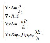
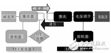
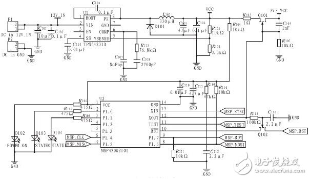
With the rise and popularity of smartphones, people are becoming more and more dependent on mobile phones. However, limited by the limitations of battery technology, the charging frequency of mobile phones has been drastically reduced with the expansion of functions. From the original two or three days, the charge has dropped to the current day, and even less. The emergence of wireless charging technology makes the charging process more convenient, and also solves the compatibility problem between different mobile phones. At present, the mainstream wireless charging technology mainly includes the following three categories: 1) Electromagnetic induction: a coil with an oscillating circuit characteristic is used to form a set of transmitting and receiving coils in two devices, and an alternating current of several megahertz is added to the coil of the transmitting device, and then the coil of the receiving device is generated. Inductive electromotive force is achieved, thereby achieving wireless transmission of electrical energy. At present, the wireless charging technology based on electromagnetic induction has a transmission power of several watts to several hundred watts and a transmission distance of less than 1 cm. 2) Radio waves: According to the principle of electromagnetics, it is known that the vertical conductor rods pass through the ultra-high frequency alternating current, and electromagnetic waves are formed around them. At a specific frequency, we call this conductor rod to emit radio waves. If a circular coil is used as an antenna and placed in a periodically varying magnetic field of a radio wave, a corresponding current is induced in the coil. The radio wave-based wireless charging technology utilizes the principle that the radio wave energy can be transmitted and received through the antenna, and the AC waveform of the radio wave is directly converted into a direct current in the rectifying circuit and used. The radio wave-based wireless charging technology has a transmission power of less than 100 mW and a transmission distance of up to 10 m. 3) Electromagnetic resonance mode: energy can be effectively transmitted between two objects with the same resonant frequency, and the interaction between objects of different frequencies is weak. Based on this principle, the MIT research team used two copper coils as the electromagnetic resonance device in the bulb test. One of the coils is connected to the power source as a transmitter and the other coil is connected to the bulb as a receiver. After power-on, the transmitter can vibrate at a frequency of 10 MHz, but it does not emit electromagnetic waves outward, but instead forms a strong non-radiative magnetic field around it. This non-radiative magnetic field can be coordinated with the receiving coil for energy transfer. The electromagnetic charging technology based on wireless magnetic resonance technology can reach several kilowatts and the transmission distance can reach several meters. This article uses TI's BQ500410A chip to form the TX end of the wireless charging system, and the RX end uses TI's BQ51013B. The solution uses three transmit coil arrays to extend position freedom while providing parasitic metal detection (PMOD) and foreign object detection (FOD) to ensure the safety of the charging process. 1 principle introduction 1.1 Transmission principle The wireless charging technology based on electromagnetic induction is similar to the transformer, and is based on the principle of electromagnetic induction. Classical electromagnetics can be summarized as a group of well-known Maxwell's equations, namely: It can be seen from the above Maxwell's equations that a changing electric field produces a changing magnetic field, and a changing magnetic field also produces a changing electric field. Repeatedly, an electromagnetic field is formed. With a wavelength as the boundary, in the wavelength range centered on the field source, it becomes the near-field region, also called the induction field; the range beyond one wavelength becomes the far-field region, also known as the radiation field. The electromagnetic field in the induction field is strong, but the attenuation is fast; on the contrary, the electromagnetic field strength in the radiation field is small, but the attenuation is slow. This principle is applied to wireless charging technology based on electromagnetic induction. The transmitting end uses the inverter technology to invert the rectified DC power into a high-frequency alternating current, so that an alternating magnetic field is generated around the transmitting coil. The receiving coil located in the induction field generates an induced electromotive force due to the action of electromagnetic induction, and is rectified and shaped for use by the load. 1.2 system structure A complete wireless charging system consists of two parts, the TX end and the RX end. The block diagram of the structure is shown in Figure 1. The structure of wireless charging is similar to an air core transformer, and energy transfer is achieved by means of coil coupling. Usually, the transmitting coil and its driving circuit are mounted in a charging board, and the receiving coil and its driving circuit are embedded in a device to be charged, such as a smart phone. The efficiency of energy transfer is related to the distance between the coils, the degree of coil alignment, the coil direction, the coil material, the magnetic field shielding, the impedance matching, the transmission frequency, and the duty cycle. Among them, the distance between the coils and the degree of alignment have a great influence on the transmission efficiency. Figure 1 Wireless charging system block diagram This article uses three transmit coil arrays to extend the charging area for better charging efficiency and experience. The BQ500410A sequentially enables three transmit coils at 400 ms intervals while enabling the analog switch of the corresponding COMM feedback signal path. The BQ500410A will look for the strongest COMM feedback signal and then drive the corresponding transmit coil to get the best coil match. Therefore, only one transmitting coil is active at the same time, and the other two transmitting coils are in a standby state. In order to reduce the electromagnetic radiation, the wireless charging system also adds a ferrite magnetic spacer to the back of the coils at both ends of the transmitting and receiving, so that the energy transmission area is confined between the two magnetic isolation sheets, thereby avoiding the wireless charging system. Radiation generated during work can interfere with smartphones or other devices. 1.3FOD and PMOD External object detection (FOD) and parasitic metal detection (PMOD) are another major feature of this design. Metal objects in the alternating magnetic field will generate eddy currents, so for safety reasons, it is necessary to detect the presence of external objects and parasitic metals between the TX terminal and the RX terminal in real time. When the system is working, the BQ500410A monitors the input voltage and input current in real time and calculates the input power. At the same time, the BQ51013B also monitors the charging voltage and charging current in real time, and feeds the output power to the BQ50041A through the communication protocol. The BQ50041A can configure the loss threshold through the resistor. If the difference between the input power and the output power is greater than the loss threshold, the BQ50041A will alarm and abort the energy transfer. 1.4 low power consumption This article achieves low power consumption of the system by adding TI's MSP430 low-power MCU to the BQ500410A. In order to achieve low power consumption, one of the most direct methods is to turn off the power directly when no load is used to completely shut down the BQ50041A. However, in doing so, the state of charge, error status, operating mode, and drive pin status information will be completely lost. After the MSP430 is added, the BQ500410A can be periodically powered off to save power. The wake-up signal is provided by the MSP430. At the same time, various status information is also saved by the MSP430, and the LED status indicator is also driven by the original BQ500410A to be driven by the MSP430. As a result, although the complexity and cost of the system are improved, the standby power consumption is reduced from the original 300mW to about 90mW. Figure 2 low power circuit 2 Conclusion The wireless charging system proposed in this paper solves the problem of small charging area of ​​the traditional single-coil solution, and greatly improves the user experience. Therefore, the scheme of this paper has higher market value. In addition, the low-power circuit added in this paper can reduce the standby power consumption from 300mW to 90mW, which can better meet the needs of some low-power devices.
Comfortel offers the latest trendsetting designs in hairdressing furniture including salon chairs, hair wash chair, barbers chairsand Display Shelving Unit trolleys, the essential partner in unleashing your creativity and setting you apart from the rest.
Hair Salon Waiting Sofa,Waiting Room Chairs,Parlour Hair Wash Chair,Display Shelving Unit TOM SPA BEAUTY SALON EQUIPMENT CO.,LTD , https://www.tomspabeauty.com