How to reduce fiber splice joint loss Definition: A certain amount of loss caused by the transmission of light to the joint after the fiber is connected is called the splice loss or the splice loss. Reason: The splice loss of the fiber is mainly composed of the transmission loss of the fiber itself and the splice loss at the splice of the fiber. Since the quality of the fiber connection affects the transmission loss of the fiber line, and the transmission line distance of the fiber line is not relayed, the loss of the fiber fusion joint should be reduced as much as possible to ensure the transmission quality of the fiber CATV signal. So how do you reduce the loss of the fiber splice joint? Methods as below: 1. Try to use the same batch of high-quality brand-name bare fiber on one line. 2. Optical cable erection is carried out as required 3. Select experienced and well-trained fiber optic splicers for continuation 4. The connecting cable should be carried out in a neat environment. 5. Select high-precision fiber end face cutter to prepare fiber end face 6, the correct use of the fusion machine Threading tips in wiring In the wiring project, the level of construction directly affects the performance of the system, and serious rework, such as grooving, wrong color labeling on the patch panel, and wrong numbering, etc. For example, if the cable passes through the steel pipe and passes through the transition box, etc., it is a commonly used technology. Now we will summarize the more mature experience in this area for your reference. Threading technology is a relatively common technique in wiring. In order to ensure that the cable is not scratched and cause a "short circuit", plastic guards should be placed at all steel pipe ports. A feasible method is that the threading personnel should carry the "protecting mouth" at any time during construction, and can be placed at any time when needed, so as to avoid "lazy" because there is no "guard" at hand. When the vertical cable is turned into the vertical steel pipe through the transition box and goes to the next layer, the suspension should be tied in the transition box to avoid the cable weight being fully pressed on the inner cable of the corner, because this will affect the transmission characteristics of the cable. The cables in the vertical trunking are to be tied once per meter. The cables placed in the trunking should be straight, entangled, and consistent in length. Regarding the "remaining line" problem, the length of the "remaining line" of the cable at the wiring box should be the same, and not too long. It is best to group the remaining lines according to the grouping table, straighten and tie them from the outlet of the line slot, and the distance between the binding points is not more than 50cm. It should be noted that it is not possible to tie wires or hard power cables. Regarding the labeling problem, the cables are numbered according to the computer plan, each label corresponds to a pair of four core wires, and the corresponding room and socket positions cannot be mistaken. In practice, this is the most error-prone place. The experience is that the label position on both ends is 25cm from the end, and the light-colored plastic tape is attached. The oil-colored pen is used to write the label or the paper number is attached, and then the transparent tape is wrapped. In addition, it is generally necessary to wear a spare line in a ratio of 3%, and the spare line is placed in the trunk line slot, and at least one spare line per layer. After the threading is completed, all 4 pairs of core cables should be fully tested for continuity. The test can be carried out by peeling off the cores of the cables at both ends to expose the copper core. At one end, the digital multimeter is dialed to the on/off test file, and the two test leads are connected to a pair of cable cores, and the pair of cable cores are frequently and briefly contacted at the other end. If the end of the watch can hear intermittent sound, it means the test passes, and 4 pairs of cores of each cable are tested. Through such tests, problems such as disconnection, disconnection, and mislabeling can be found. During wiring, there is also a need to pay attention to the fact that when the cable is pulled out of the cable box and has not been placed in place, if the construction is to be suspended, the cable should be carefully wrapped and retracted for safekeeping. This is a place that many wiring construction teams without standard management often overlook.
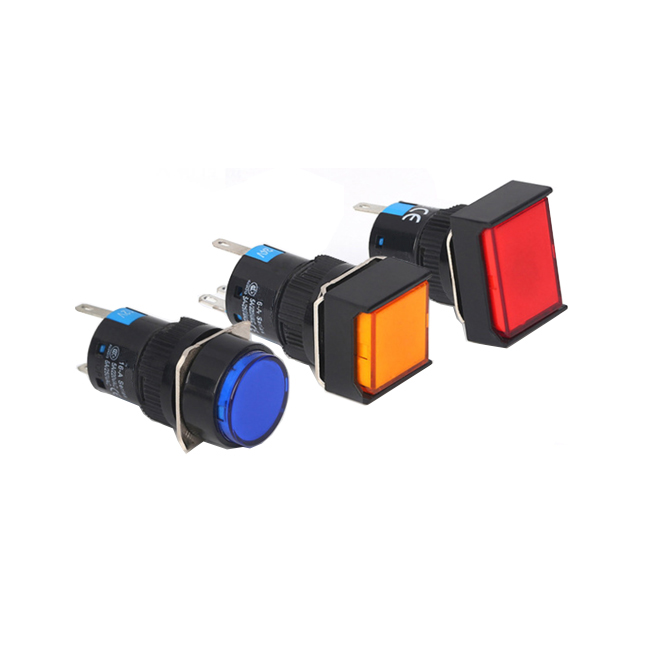
SDL16 series 16mm installation Pushbutton Switch refers to an electronic component that can open a circuit, interrupt current, or flow it to other circuits.We also called it for LA137-H series Pushbutton Switch,can be designed according to customer's needs.
The push button series are used in controlling circuit of AC voltage up to 660V/AC 50Hz~60Hz,and DC voltage below 400V.It is used for controlling signal and interlocking purposes.
SDL16 Plastic Pushbutton Switch SDL16 Series Pushbutton Switch,Push Button Light Switch,Mushroom Push Button Switch,Red Mushroom Head Pushbutton Switch Ningbo Bond Industrial Electric Co., Ltd. , https://www.bondelectro.com
They adopting the non-contacting accessories,self-locked contacting type,safe and reliable,and separate conveniently.Its shape is handsome, specially designed for industrial equipment, have firm fabrics, and have very good quality and very competitive prices. The switches have full and different kinds for different functions, like spring return type,self-locked type,with lamp type,mushroom head type,selector type,with key type and emergency stop type,etc.
