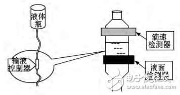
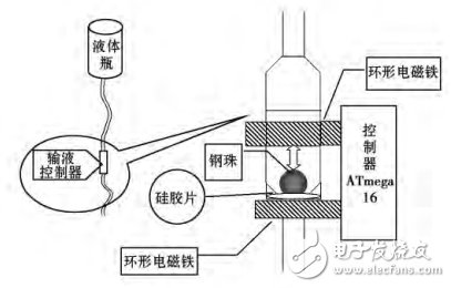
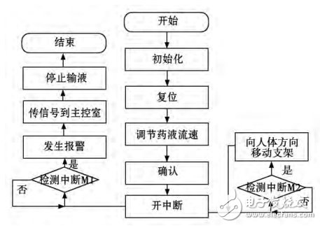
Research significance At present, hospital intravenous infusion is mainly manual control, intravenous fluids monitored by humans, can not correctly mediate the flow rate of the drug, the speed is too fast, because the potassium component in the spot will cause vascular stimulation, usually the stimulation will be pain. But usually the speed of infusion depends on your own physical condition, but the infusion will still stimulate the blood vessels and heart and kidneys. Using the existing technology to design an intelligent infusion system, it can control the flow rate of the liquid medicine, detect the remaining amount of the liquid medicine, stop the infusion in time to prevent blood return, etc., the medical staff can observe and mediate the flow rate of all the liquid medicine through the main control room, thereby greatly save human effort. This design studies an intelligent liquid drip speed controller with convenient operation, intuitive display and alarm function. This system allows the nursing staff to monitor the progress time of the patient's drip, and avoid the patient's "blood return" during the infusion process. The medical accidents improve the safety factor of the patient during the treatment of infusion, while reducing the workload of the nursing staff and giving the nursing staff a more comfortable working environment. 2. System overall design This system uses ATMEGA16 as the main control chip to control the droplet velocity, alarm information and the movement direction of the liquid rack. The infusion set can set the drip speed arbitrarily through the remote controller, and can receive the information set by the remote controller and can perform abnormal conditions. Call the police. The system hardware block diagram is shown in Figure 1. The lower position system adopts modular design ideas, including liquid level detection and alarm system, drip speed system (including drip speed control device, steel ball and other actuators), single chip processing system, communication module, custom remote control module, display and alarm. Module, angle sensing module and other parts. The liquid level detecting module is mainly used for alarming the liquid level, the actuator performs the drip speed control under the control of the program; the communication module is used for communication with the host. Figure 1 hardware block diagram 2.1 Droplet detection program The drip rate test uses an infrared detection technique to measure the infusion rate above the Muffin's dropper. The structure diagram of the drip rate detecting device is shown in Figure 2. After the infrared emitter emits infrared light, the light penetrates the Muffin's dropper and is irradiated onto the phototransistor. The phototransistor turns the light that is irradiated onto it into a current signal for output. If there is no droplet drop in the Moffett dropper at this time, the attenuation of the light is relatively small, and the current on the triode is relatively large; if there is a drop in the Muffin dropper at this time, the droplet is blocked. In the case of light, the droplets absorb and scatter light, causing the phototransistor to receive a relatively weak optical signal. The current signal outputted by the phototransistor is converted into a voltage signal, and the presence or absence of the drop of the liquid droplet can be detected by detecting the strength of the voltage signal at the output end. After the detected signal is shaped and sent to the MCU for processing, the drip rate of the infusion can be calculated. Figure 2 Droplet speed detection device structure 2.2 Drop speed control scheme The electromagnet and the small steel ball in the observation bottle and the corresponding control circuit form a motor with a "creeping" effect to control the liquid dripping speed, which can achieve precise control of the droplet, using the "peristaltic" motor structure and liquid level. The sensor realizes the function of automatically closing the liquid path in a timely and accurate manner when the liquid medicine is short, and prevents the phenomenon of "returning blood". The schematic diagram of the drip speed control device is shown in Figure 3. Figure 3 Schematic diagram of the drip speed control device 3. Program flow chart In order to facilitate the development of the program and the subsequent use and maintenance, all the programs adopt a modular structure, that is, a main program and a plurality of sub-program modules. The main program first completes the initialization work, including timer initialization, LCD module initialization, interrupt initialization, system clock initialization, initialization of other parameters, and so on. The timer is then started for timing, and the open interrupt allows the microcontroller to respond to internal interrupts and external interrupt requests. Each program function module includes liquid crystal display, motor drive, alarm control, drip speed detection, liquid level detection and the like. The main program flow chart is shown in Figure 4. Figure 4 main program flow chart The entire system software uses a modular structure. The slave software system includes: main program: responsible for reading keys, displaying and alarming. Communication interrupt program: realize communication with the master station. The drip speed sampling and the liquid storage bottle are detected by the human body movement, wherein the M1 detects the liquid level condition, the interruption stops the infusion, generates an alarm, interrupts the M2 to detect the moving direction of the human body, and if an interruption occurs, the single chip outputs a PWM pulse, thereby controlling the motor to drive. The reservoir bottle moves in a directional orientation. Ensure that the reservoir is permanently above the body. The program of the master station includes a main program and a communication interrupt program, wherein the main program is responsible for setting the slave station, displaying the real-time value from the slave station, and being responsible for the alarm. The communication interruption program is responsible for communicating with the slave station to realize real-time data collection. 4. Summary The system uses ATMECA16 control chip to simplify the hardware structure of the system and improve the reliability and real-time of the system. The use of "creeping" motor structure and liquid level sensor realizes the timely and accurate automatic closing of the liquid path function when the shortage of liquid medicine, preventing the occurrence of "blood return" phenomenon. When the liquid medicine is short, the user end uses the sound and light reminder when the liquid circuit is closed, and the relevant information is sent to the duty room through wireless transmission, and the medical staff on duty is notified in time. It saves a lot of manpower and material resources and reduces human error. This system has certain guiding significance for practical engineering applications.
Our Cable Tester including Cable Tester, Coax Cable Tester, Lan Cable Tester, Fiber cleaver, Network Multi-Modular Cable Tester, Fiber Checker, Optical Power Meter, Optical Fiber Identifier, Optical Fiber Ranger.
A cable tester is an electronic device used to verify the electrical connections in a cable or other wired assembly. Generally a cable tester consists of:
1.A source of electric current,
Cable Tester Cable Tester, Multi-Modular Cable Tester, RJ45 Modular Cable Tester, Fiber cleaver, Network Multi-Modular Cable Tester, Fiber Checker NINGBO YULIANG TELECOM MUNICATIONS EQUIPMENT CO.,LTD. , https://www.yltelecom.com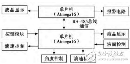
2.A volt meter,
3.A switching matrix used to connect the current source and the volt meter to all of the contact points in a cable.
In addition to these parts a cable tester may also have a microcontroller and a display to automate the testing process and show the testing results.
