Chapter 1: Fieldbus Technology and Profibus 1.1.2 On-site and workshop-level automation monitoring and information integration is an indispensable part of factory automation and CIMS. Figure 1-2: Traditional field-level and shop-level automation monitoring and information integration systems 1.1.4 Main disadvantages of the system (1) The information integration capability is not strong: the controller and the field device are connected by I/O connection, and transmit 4-20 mA analog signal or 24 VDC switch signal, and monitor the field device accordingly. . In this way, the controller obtains a limited amount of information, and a large amount of data such as device parameters, faults, and fault records are difficult to obtain. The underlying data is incomplete and the information integration capability is not strong enough to fully meet the requirements of the CIMS system for the underlying data. 1.2.4 Fieldbus-based automation monitoring and information integration system main advantages (1) Enhanced field-level information integration capability Fieldbus can obtain a large amount of rich information from field devices, which can better meet the information integration requirements of factory automation and CIMS systems. . The fieldbus is a digital communication network. It does not simply replace the 4-20 mA signal, but also implements device status, fault, and parameter information transmission. In addition to completing the remote control, the system can also perform remote parameterization work. (1) Profibus-DP: defines the first, second and user interfaces. The third to seventh layers are not described. The user interface specifies the user and system and the application functions that can be called by different devices, and details the device behavior of various PROFIBUS-DP devices. Figure 2-2: Cable and bus terminating resistors for PROFIBUD-DP and Profibus-FMS Figure 2-2: Up to 32 stations (master or slave) can be connected to each segment (5) The maximum cable length depends on the transmission rate. If a type A cable is used, the transmission rate and length are as shown in Table 2-1: (6) Type A cable parameters: Figure 2-3 (3) The field distribution box continues to be used to connect field devices and place bus terminating resistors. When using the tree structure, all field devices connected to the fieldbus segment are connected in parallel to the field distribution box. (8) External power supply: If an external power supply device is equipped with an appropriate isolation device according to the EN50020 standard, it is permissible to connect the bus-powered device to the external power supply device on the intrinsically safe bus. Dry Type Transformer,Dry Transformer,Medium Voltage Dry Type Transformers,Dry Type Distribution Transformer Tianhong Electric Power Technology Co., Ltd , https://www.tianhongtransformer.com
1.1 The origin of fieldbus technology 1.1.1 CIMS architecture and industrial data structure hierarchy According to factory management, production process and functional requirements, CIMS architecture can be divided into 5 layers, namely factory level, workshop level, unit level, workstation level and Field level. The simplified CIMS is divided into three layers, namely the factory level, the workshop level and the field level. In a modern factory environment, industrial data structures are equally divided into these three levels in large-scale industrial production process control, corresponding to a simplified network hierarchy. As shown in Figure 1-1. 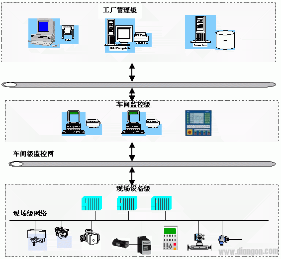
Figure 1-1: Simplified CIMS Network Architecture
The on-site and workshop-level automation monitoring and information integration system mainly completes the single-machine control, connected control, communication networking, online equipment status monitoring, field device operation, production data collection, storage, statistics and other functions of the underlying equipment to ensure high field equipment. Quality completes the production task and transmits field device production and operational data information to the plant management to provide data to the plant-level MIS system database. Production management and scheduling orders issued by the plant management are also accepted and executed. Therefore, field-level and shop-level monitoring and information integration systems are the foundation for implementing plant automation and CIMS systems.
1.1.3 Traditional on-site and workshop-level automation monitoring and information integration systems Traditional field-level and workshop-level automation monitoring and information integration systems (including: distributed control systems based on PC, plc, dcs products), its main features First, the connection between the field device and the controller is one-to-one (one I/O point to the device's measurement and control point). The so-called I/O wiring mode, signal transmission 4-20mA (transmit analog information) or 24VDC (Transfer switch amount information) signal. As shown in Figure 1-2: 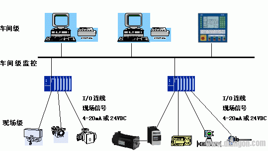
(2) The system is not open, the integration is poor, and the professionalism is not strong: except for the field devices, which are connected by standard 4-20mA/24VDC, other software and hardware of the system can only use one product. Lack of interoperability and interchangeability between different manufacturers' products, so they can be poorly integrated. Such systems rarely leave interfaces, allowing other vendors to integrate their own proprietary control technologies, such as control algorithms, process flows, recipes, etc. into a common system. Therefore, there are few monitoring systems for the industry.
(3) Reliability is not easy to guarantee: For a wide range of distributed systems, a large number of I/O cables and installation workers not only increase the cost, but also increase the system's unreliability.
(4) The maintainability is not high: due to incomplete information of the field-level equipment, the online fault diagnosis, alarm, and recording functions of the field-level equipment are not strong. On the other hand, it is difficult to complete the parameterization functions such as remote parameter setting and modification of field devices, which affects the maintainability of the system.
1.1.5 The serial communication interface of field devices is the prototype of fieldbus technology. Due to the development of large-scale integrated circuits, many field devices such as sensors, actuators, and drive devices are intelligent, that is, built-in CPU controllers, such as linearization and range. Conversion, digital filtering and even loop adjustment. Therefore, it is very convenient to add a serial data interface (such as RS-232/485) to these intelligent field devices. With such an interface, the controller can perform monitoring of the field devices by serial communication (rather than I/O mode) according to its specified protocol. If all or most of the field devices are assumed to have a serial communication interface and a uniform communication protocol, the controller can connect all the field devices with a single communication cable to complete the monitoring of all field devices. This is the fieldbus. The initial idea of ​​technology.
1.2.4 Fieldbus technology generation Based on the above initial idea, a communication cable is used to connect all field devices with a unified communication protocol communication interface, so that the I/O (4-20mA) is no longer transmitted at the device layer. /24VDC) signal, but based on fieldbus digital communication, the digital communication network constitutes the field level and workshop level automation monitoring and information integration system.
1.2 Fieldbus Technology Concepts 1.2.1 Fieldbus Technology At present, the recognized fieldbus technology concept is described as follows: Fieldbus is a string between field devices/meters installed in the production process area and automatic control devices/systems in the control room. Data bus for line, digital, and multipoint communication. Among them, the "production process" includes two types of intermittent production process and continuous production process.
Alternatively, the fieldbus is a network system and control system that implements automatic control functions by using a single distributed, digitized, intelligent measurement and control device as a network node, connected by a bus, to exchange information with each other.
1.2.2 The significance of fieldbus technology generation (1) Fieldbus technology is an industrial field layer network communication technology for realizing digital communication of field level control equipment; it is a digital revolution of industrial field level equipment communication. Fieldbus technology can use a communication cable to connect field devices (intelligent, with communication interface), replace 4-20mA/24VDC signals with digital communication, and complete field device control, monitoring, remote parameterization and other functions.
(2) The traditional field-level automatic monitoring system adopts one-to-one wired, 4-20mA/24VDC signals, and the amount of information is limited. It is difficult to exchange information between devices and between the system and the outside world, making the automatic control system become a factory. The “information island†seriously restricts the realization of enterprise information integration and enterprise integrated automation.
(3) The fieldbus-based automatic monitoring system adopts computer digital communication technology to make the automatic control system and equipment join the factory information network, which constitutes the bottom of the enterprise information network, and extends the coverage of enterprise information communication to the production site. In the CIMS system, the fieldbus is an extension of the plant computer network to the field level equipment, and is the technical basis to support the integration of field level and workshop level information.
1.2.3 Field-level and workshop-level automation monitoring and information integration system based on fieldbus The field-level and workshop-level automation monitoring and information integration system based on fieldbus technology is shown in Figure 1-3: 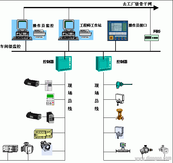
Figure 3: Fieldbus-based field-level and shop-level automation monitoring and information integration system
(2) Open, interoperability, interchangeability, and integration. As long as the products of different manufacturers use the same bus standard, they are interoperable and interchangeable, so the device has good integration. The system is open, allowing other vendors to integrate their own proprietary control technologies, such as control algorithms, process flows, recipes, etc. into a common system. Therefore, there will be many monitoring systems for the industry in the market.
(3) High system reliability and maintainability The fieldbus-based automatic monitoring system uses bus connection instead of one-to-one I/O connection. For large-scale I/O systems, the number of connection points is reduced. Unreliable factors. At the same time, the system has online fault diagnosis, alarm and recording functions of field-level equipment, which can complete the parameterization of remote parameter setting and modification of field devices, and also enhance the maintainability of the system.
(4) Reduced system and engineering costs For large-scale, large-scale I/O distributed systems, a large number of cables, I/O modules, and cable laying engineering costs are eliminated, reducing system and engineering costs.
1.3 Fieldbus Standard Fieldbus technology is a key issue to be realized in the automation industry to form a fieldbus communication protocol technology standard that manufacturers can abide by. Manufacturers can follow standard products, and system integrators can follow The standard combines different products into a system. This raises the issue of fieldbus standards. The internationally renowned manufacturers of automation products and field devices realize that fieldbus technology is the future development direction, and they have formed alliances of enterprises, launched their own bus standards and products, cultivated users in the market, expanded their influence, and actively supported the International Standards Organization. Develop fieldbus international standards. Whether it can make its own bus technology standard occupy a large proportion in future international standards, which is related to the future of the company's related products, the trust of users and the reputation of the company. Historical experience has proven that international standards are based on one or several of the most successful technologies on the market. Therefore, the competition of major international companies in the development of fieldbus international standards reflects the competition of companies in the leading position of technology, and ultimately it must be attributed to the competition of market strength.
It is said that there are currently more than 200 kinds of bus and bus standards available in the world. There are several types of buses that have certain influence and already occupy a certain market share:
1.3.1 Profibus fieldbus was approved on March 15, 1996 as the European standard, DIN 50170V.2. Profibus products have been widely accepted in the world market, with market share ranking first in Europe, with an annual growth rate of 25%. At present, there are more than 1,500 products supporting the PROFIBUS standard, which are from more than 250 international manufacturers. More than 2 million PROFIBUS devices have been installed and operated worldwide. By May 1998, PROFIBUS-PA instrumentation for process automation was put into operation on site in 40 user manufacturers in 19 countries. In 1985, the PROFIBUS International Support Center was established; in December 1989, the PROFIBUS User Organization (PNO) was established. At present, 20 regional user organizations have been established in the world, with nearly 650 corporate members. In July 1997, the China Fieldbus (PROFIBUS) Professional Committee was established, and a laboratory for fieldbus PROFIBUS product demonstration and certification was established.
The main application areas of Profibus are:
. Manufacturing automation: automotive manufacturing (robots, assembly lines, press lines, etc.), paper, textiles.
. Process control automation: petrochemicals, pharmaceuticals, cement, food, beer.
. Electricity: power generation, transmission and distribution.
. Buildings: air conditioning, fans, lighting.
. Railway Traffic: Signal System 1.3.2FF Fieldbus In 1994, the FF Foundation was formed by the merger of the ISP Foundation and WorldFIP (North America). Its purpose is to develop the only international fieldbus (FundationFieldbus) that complies with IEC and ISO standards. . The Low Speed ​​Bus (H1) protocol was published in 1996. The high-speed bus (H2) that has been developed is intended to be in 1998. In May 1997, the China Fieldbus (FF) Professional Committee was established and the FF Fieldbus Product Certification Center was established. At present, the application field of FF fieldbus is mainly process automation. Such as: chemical, power plant experimental systems, wastewater treatment, oil fields and other industries.
1.3.3 LONWORKS bus LONWORKS field bus is called LONWORKSNetWorks, which is distributed intelligent control network technology. It is hoped to introduce a measurement and control network that can be adapted to various fieldbus applications. LONGWORKS currently has a wide range of applications, including industrial control, building automation, data acquisition, and SCADA systems. Domestically, it is mainly used in building automation.
1.3.4 CANBUS Fieldbus The CANBUS fieldbus has been approved by the ISO/TC22 Technical Committee as the international standard IOS11898 (communication rate less than 1Mbps) and ISO11519 (communication rate less than 125Kbps). CANBUS's main products are used in automotive manufacturing, public transportation vehicles, robotics, hydraulic systems, and distributed I/O. In addition, it is used in elevators, medical equipment, machine tools, building automation and other occasions.
1.3.5 WorldFIP Fieldbus 90-91 FIP fieldbus became the national safety standard of France. In 1996, it became the European standard (EN50170V.3). The next step is to be close to the IEC standard and is now fully technically prepared. WorldFIP International has an office in Beijing, the WorldFIP China Information Center, which is responsible for China's technical support. WorldFIP fieldbus uses a single bus structure to accommodate different application areas, with different application rates using different bus speeds. The process control is 31.25Kbit/s, the manufacturing is 1Mbit/s, and the drive control is 1-2.5Mbit/s. The bus arbiter and priority are used to manage the communication of the various control stations on the bus (including the various branches). Multiple communication methods such as one-to-one, one-to-many (group), and one-to-all can be performed. In the application system, a dual bus structure can be adopted, in which one bus is a backup line, which increases the security of the system operation.
WorldFIP fieldbus is used in a wide range of applications, including process automation, manufacturing automation, power and building automation.
1.3.6 P-NET Fieldbus P-NET Fieldbus was built in 1983. In 1984, the first products using multi-master fieldbus were introduced. Multiple network structures and multiple interface functions were added to the 1986 communication protocol. In 1987, P-NET's multi-interface products were introduced. In 1987, the P-NET standard became an open and complete standard and became the national standard of Denmark. In 1996 it became part of the European bus standard (EN50170V.1). In 1997, the company established an international P-NET user organization with nearly 100 corporate members. It is headquartered in Siekeborg, Denmark, and has regional organization branches in Germany, the United Kingdom, Portugal and Canada. P-NET fieldbus is widely used in Europe and North America, including petrochemical, energy, transportation, light industry, building materials, environmental engineering and manufacturing applications.
1.4 How to face many fieldbus standards Faced with fieldbuses and standards of various international genres, in order to deeply study foreign advanced fieldbus technology, promote the research and development of China's fieldbus technology and products, form a reality and reality in line with China's national conditions The standard system protects the investment efficiency of China's production enterprises and users. The supervisory unit of China's instrument standardization industry-instrumentation comprehensive technology and economic research institute follows the standardization work procedure, and has been in Beijing China Technology since July 22, 1998. The seminar hall held a seminar on "Standardization of Fieldbus and Development of China's Automation Technology". The conference invited representatives of Profibus, FF, WorldFIP, and P-NET international organizations to introduce the international popular fieldbus technology and standardization. At the seminar, Chinese and foreign experts launched a hot discussion on the development of fieldbus international standardization, and put forward the following opinions and opinions:
(1) It is expected that the IEC will complete the development of uniform standards as expected as soon as possible.
(2) According to current progress estimates, it is difficult for IEC to achieve the expected targets in recent years.
(3) At present, the proposed scheme proposed by the IEC is limited to process automation, it is difficult to meet the requirements of other application fields, and it is impossible to become the sole standard, and it is likely that a plurality of standard systems coexist.
(4) Making multiple communication protocol interfaces under the unified standard framework may be a suitable solution for unified standards.
Experts and representatives believe that in the development of fieldbus technology policy in China, combined with China's national conditions, on the one hand, we should actively track the development of IEC international standardization and carry out technical research and product development in China. On the other hand, before the unified IEC standard is formed, it will actively carry out research on other advanced fieldbus technologies, especially the fieldbus technology with mature application experience and large coverage of application fields.
1.5 Talk to the users who are facing the choices and make suggestions. From the user's point of view, how to face the choice of many fieldbus standards, the author hereby expresses personal opinions and puts forward some suggestions for users' reference.
(1) Standard? From the history of standard development, whose technology will become an international standard or occupy a larger component in international standards depends mainly on how much it achieves in practical applications, depending on the technology and products in the international market. Occupy share. In other words, whoever can occupy the market will win the world. On the other hand, according to the rapid development of science and technology and the requirements of manufacturers for standards, the International Organization for Standardization has made corresponding changes to the formulation and approval procedures of standards, which simplifies the procedures and procedures for standard setting, and acknowledges the existence of so-called facts. The standards, that is, the technical standards that have a large share in the market and have great experience in successful application of users, such as the TCP/IP communication protocol standard we are familiar with.
(2) Select the bus? In the current situation of the field bus in the international community, users should choose from the characteristics of practical application engineering. Because there is no fieldbus technology that is comprehensive and suitable for all applications. The application performance of this bus in the industry should be emphasized. For example, manufacturing automation, power automation and process control automation are very different in terms of real-time data response requirements.
(3) Select a product? Users should try to choose company products with high international reputation, large number of users and good product application base, because the fieldbus technology of these companies is highly likely to be adopted by international standards. Even if it is not adopted by international standards, large companies will put forward the interface between the original technology and international standards in order to consider the credibility, and will not ignore the company's reputation and lose old customers.
(4) Actively track and be bold! If the international IEC does not have a unified fieldbus standard, it is not necessary to use this advanced technology. This will cause the company to lose the opportunity to improve the level of enterprise automation as soon as possible, or to lose the opportunity to improve the level of the company's products, which will lead to a disadvantage in the future competition. It is not a one-off event for the international IEC to unify the fieldbus standard. It is the best policy to wait for the opportunity to pass. Only active tracking and courageous parties are the best strategy for enterprise development.
Chapter 2: Fieldbus Profibus Technical Points This chapter outlines the main points of PROFIBUS technology from the perspective of Profibus protocol standards. Allows readers to quickly understand the PROFIBUS technology overview.
2.1Profibus overview
(1) Profibus is an international, open, fieldbus standard that does not depend on equipment manufacturers. It is widely used in manufacturing automation, process industry automation, and automation in other areas such as buildings, transportation, and electric power.
(2) Profibus consists of three compatible parts, namely PROFIBUS-DP (DecentralizedPeriphery), PROFIBUS-PA (ProcessAutomation), PROFIBUS-FMS (FieldbusMessageSpecification).
(3) Profibus-DP: is a high-speed, low-cost communication for device-level control systems and distributed I/O communication. Use PROFIBUS-DP to replace 24VDC or 4-20mA signal transmission.
(4) Profibus-PA: Designed for process automation, the sensor and actuator can be connected to a single bus with intrinsic safety regulations.
(5) Profibus-FMS: used for workshop-level monitoring network, is a token structure, real-time multi-master network.
(7) Profibus is a fieldbus technology used for factory automation workshop level monitoring and field device layer data communication and control. Decentralized digital control and field communication network for field-to-floor monitoring at the plant level provides a viable solution for comprehensive plant automation and field device intelligence.
2.2PRFIBUS basic characteristics
2.2.1 Profibus protocol structure
The Profibus protocol structure is based on the ISO7498 international standard and uses the Open System Interconnection (SIO) as a reference model. The model has seven layers, as shown in Figure 2-1 below: 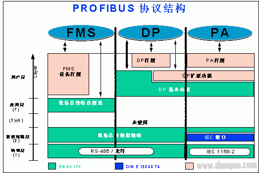
Figure 2-1: Profibus Protocol Structure
(2) Profibus-FMS: The first, second and seventh layers are defined. The application layer includes Fieldbus Message Specification (FMS) and Low Layer Interface (LLI). FMS includes application protocols and provides users with a wide range of powerful communication services. The LLI coordinates different communication relationships and provides a device-independent Layer 2 access interface.
(3) Profibus-PA: PA data transmission uses the extended PROFIBUS-DP protocol. In addition, the PA also describes the PA profile for field device behavior. According to the IEC1158-2 standard, PA's transmission technology ensures its intrinsic safety and power is supplied to field devices via the bus. Use a connector to extend the PA network on the DP.
2.2.2 Profibus transmission technology
Profibus offers three types of data transfer:
• RS485 transmission for DP and FMS.
• IEC1158-2 transmission for PA.
·optical fiber
2.2.2.1 RS485 transmission technology for DP/FMS Since the DP and FMS systems use the same transmission technology and a uniform bus access protocol, the two systems can operate simultaneously on the same cable.
RS-485 transmission is one of the most commonly used transmission technologies in Profibus. This technique is often referred to as H2. The cable used is a shielded twisted pair copper wire.
Basic features of RS-485 transmission technology:
Network topology: Linear bus with active bus termination resistors at both ends.
· Transmission rate: 9.6Kbit/s~12Mbit/s
• Media: Shielded twisted pair cable can also be unshielded depending on environmental conditions (EMC).
· Number of stations: 32 stations per segment (without relay), up to 127 stations (with relay).
• Plug connection: It is best to use a 9-pin D-type plug.
2.2.2.2 RS-485 transmission equipment installation points
(1) All devices are connected to the bus.
(2) Up to 32 stations (master or slave) can be connected to each segment.
(3) Each segment has a bus terminating resistor at the head and tail to ensure that there is no error in operation. Both bus terminating resistors must always have a power supply. See Figure 2-2.
(4) When there are more than 32 segment stations, a repeater must be used to connect the bus segments. There are usually no more than three repeaters in series. See Figure 2-3: 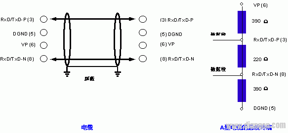
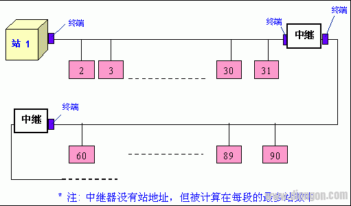
table 2-1
Impedance: 135-165W Capacitance: <30pf/m loop resistance: 110W
Wire gauge: 0.64mm wire area: >0.34mmW
(7) The Profibus network for RS-485 transmission technology is best to use a 9-pin D-type plug. The pin definition and wiring are shown in Figure 2-2.
(8) When connecting the stations, make sure that the data lines are not twisted. The system should be operated with a shielded cable in a high electromagnetic emission environment (such as the automobile manufacturing industry). Shielding can improve electromagnetic compatibility (EMC).
(9) If shielded braided wire and shielding foil are used, they should be connected to the protective ground at both ends and covered by the shielded wiring as large as possible to maintain good conductivity. It is also recommended that the data line be isolated from the high voltage line.
(10) Short-cut segments should be avoided when the data transmission rate exceeds 500Kbit/s. The existing input plugs on the market should be used to connect the data input and output cables directly to the plug, and the bus plug can be turned on or off at any time. Open without interrupting data communication at other stations.
2.2.2.3 IEC1158-2 transmission technology for PA
(1) Data transmission technology of IEC1158-2 is used in Profibus-PA to meet the requirements of the chemical and petrochemical industries. It maintains its intrinsic safety and powers field devices over the bus.
(2) IEC1158-2 is a bit synchronization protocol, commonly referred to as H1.
(3) IEC1158-2 technology is used for Profibus-PA, and its transmission is based on the following principles:
• There is only one power supply per section as the power supply unit.
• When the station sends and receives information, it does not supply power to the bus.
• The constant current basic current is consumed by each station's field device.
• Field devices act like passive current sinks.
• Both ends of the main bus function as passive terminal lines.
· Allow the use of linear, tree and star networks.
• To improve reliability, redundant bus segments can be used in the design.
• For modulation purposes, assume that each bus station requires at least 10 mA of basic current to start the device. The communication signal is generated by the modulation of the transmitting device, from ±9mA to the basic current.
(4) IEC1158-2 transmission technology features:
Data transmission: digital, bit synchronization, Manchester coding.
· Transmission rate: 31.25Kbit/s, voltage type.
Data reliability: Preamble, using start and end qualifiers to avoid errors.
• Cable: Twisted pair, shielded or unshielded.
Remote power supply: optional accessories, through the data line.
· Explosion-proof type: It can perform intrinsic and extrinsic safety operations.
Topology: line or tree, or a combination of both.
· Number of stations: Up to 32 per segment, with a total of up to 126.
• Repeater: Up to 4 units can be expanded.
2.2.2.4 IEC1158 transmission equipment installation points
(1) The segmentation coupler connects the IEC1158-2 transmission technology bus segment with the RS-485 transmission technology bus segment. The coupler adapts the RS-485 signal to the IEC1158-2 signal. They supply remote power to field devices, and the power supply limits the current and voltage of the IEC1158-2 bus.
(2) The network topology of Profibus-PA has a tree and line structure, or a mixture of two topologies, as shown in Figure 2-3. 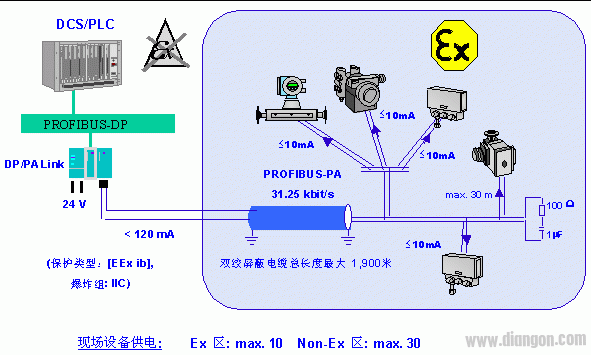
(4) It is recommended to use the following reference cables, or other cables with thicker section conductors.
· Cable design: twisted pair shielded cable · wire area (rated value): 0.8mm2 (AWG18)
·Circuit resistance (DC): 44W/Km
· Impedance (31.25 kHz): 100W ± 20%
· 39 kHz attenuation: 3dB/Km
·Capacitance imbalance: 2nF/Km
(5) There is a passive terminator at each end of the main bus cable, which has RC components connected in series, R=100W, C=1mF. When the bus station polarity is reversed, it does not have any effect on the function of the bus.
(6) The maximum number of stations connected to a segment is 32. If intrinsically safe and bus powered, the number of stations will be further limited. Even if intrinsic safety is not required, the power supply to the remote power supply unit is limited.
(7) Determine the longest length of the line. Calculate the current requirement according to the experience. Select a power supply unit from Table 2-2, and select which cable according to the length of the line in Table 2-3.
Table 2-2 Standard power supply unit (operating value)
Table 2-3 Line length of the transmission equipment of IEC1158-2
2.2.2.5 Optical fiber transmission technology
(1) When the Profibus system is used in an environment with large electromagnetic interference, a fiber optic conductor can be used to increase the distance of high-speed transmission.
(2) Two kinds of fiber-optic conductors can be used, one is a low-cost plastic fiber conductor, and the distance is less than 50 meters. The other is a fiberglass conductor for use at distances greater than 1 km.
(3) Many manufacturers provide dedicated bus plugs to convert RS-485 signals into fiber-optic conductor signals or to convert fiber-optic conductor signals into RS-485 signals.
2.2.3 Profibus bus access protocol
(1) Three Profibus (DP, FMS, PA) use a consistent bus access protocol. The protocol is implemented through the second layer (data link layer) of the OSI reference model. It includes guaranteed data reliability techniques and transport protocols and message processing.
(2) In Profibus, the second layer is called the fieldbus data link layer (FieldbusDataLink-FDL). Media Access Control (MAC) specifically controls the process of data transmission. The MAC must ensure that only one