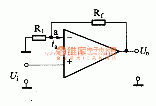
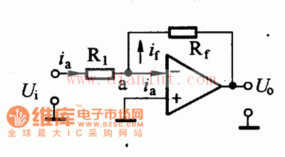
The following is the circuit diagram of [Feedback Circuit] Feedback circuit Operational amplifiers often require an external feedback circuit in practical applications. Because the open-loop gain of the op amp is very high, and the gain required in practical applications is not very high, it is necessary to add a negative feedback circuit to form a closed loop to obtain the corresponding function. In addition, the performance of the op amp is greatly improved under deep feedback conditions. Feedback amplifier circuit with non-inverting input The figure is a feedback amplifier circuit with an in-phase input. A negative feedback resistor Rf is applied from the output terminal to the inverting input terminal, and the input voltage is input from the non-inverting terminal. Since the ideal operation corrects the input impedance of the amplifier to infinity, the feedback amplifier circuit of the non-inverting input The figure is a feedback amplifier circuit with an in-phase input. A negative feedback resistor Rf is applied from the output terminal to the inverting input terminal, and the input voltage is input from the non-inverting terminal. Since the ideal operation corrects the input impedance of the amplifier to infinity, the feedback amplifier circuit of the non-inverting input The figure is a feedback amplifier circuit with an in-phase input. A negative feedback resistor Rf is applied from the output terminal to the inverting input terminal, and the input voltage is input from the non-inverting terminal. Since the input impedance of the ideal operation is corrected to infinity, ia=0, and the potential at point a is According to the open loop voltage gain expression, you can list: The above equation shows that as long as the AUD is large enough, the op amp output voltage and the input voltage become a simple multiple relationship. The closed-loop gain depends only on the resistance ratio and is independent of other parameters. Inverting input feedback amplifier circuit The circuit shown in the figure is a feedback amplifier circuit with an inverting input. A negative feedback resistor Rf is applied from the output terminal to the inverting input terminal, and the input voltage Ui is input from the inverting terminal. Since i'a=0, ia=if, ie If AUD is infinite, and U. Is a finite value, then Ua>0, that is, the point potential is close to the ground potential, at this time The negative sign in the equation indicates that the output voltage is opposite to the phase of the input voltage. The above equation shows that as long as the AUD is large enough, the closed-loop gain of this amplifier is determined only by the ratio of the resistors Rf and R1, regardless of other parameters. By introducing a large feedback amplifier to the negative feedback circuit, it is convenient to design an amplifier with precisely controlled gain, and the gain is independent of the internal parameters of the operational amplifier. High Speed Data Cable,Fast Charging Cable,Interface Cable,Usb C To Type-C Interface Cable Dongguan Pinji Electronic Technology Limited , https://www.iquaxusb4cable.com


