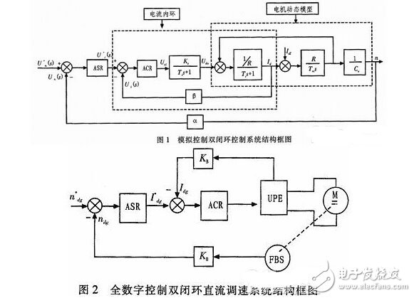
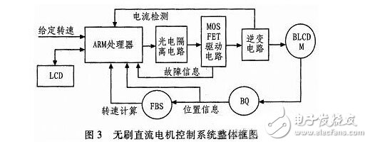
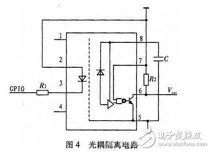
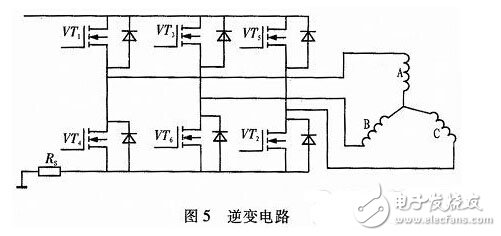
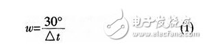
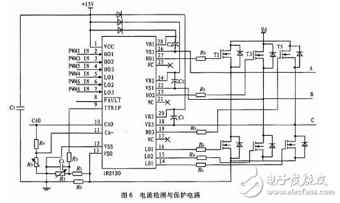
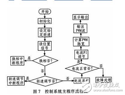
The traditional DC motor has many advantages such as high operating efficiency and good speed regulation performance, and therefore plays an important role in industrial transmission. However, its inherent mechanical commutator and brush lead to limited motor capacity, high noise and easy generation. Shortcomings such as sparks and poor reliability. With the development of computer technology and microelectronic technology, the position sensor and electronic commutator of the brushless DC motor replace the brush and mechanical commutator of the brushed DC motor, while maintaining the advantages of the traditional DC motor. It has higher operating efficiency than brushed DC motors. Therefore, once the DC brushless motor is produced, it has been widely used in industrial production. Especially in the era of energy saving and emission reduction, the high efficiency of the brushless DC motor shows its great application value. 1 Introduction to all-digital double closed-loop DC speed control system In the case of steady state, the DC motor only adopts the single closed-loop speed PI adjustment to realize that the DC speed is very stable under the premise of ensuring that the DC speed is very stable, that is, the output completely follows the input. However, when the control system with high braking speed and strong anti-interference ability has high dynamic performance requirements, the dynamic process of current and torque in the single closed-loop system cannot be controlled in time and effectively, so it needs to be set in the control system. A current regulation loop is used to regulate the current. Therefore, there are two adjustment rings of the speed adjustment ring and the current adjustment ring in the control system, and a nested connection is implemented between the two adjustment rings. Figure 1 and Figure 2 are the block diagram of the structure of the double closed-loop control system under analog control and full digital control, and the block diagram of the double closed-loop DC speed control system. 2 control system overall composition The all-digital double-closed brushless DC motor control system is mainly composed of ARM embedded processor, LCD touch screen, photoelectric coupling circuit, driving circuit, inverter circuit, current detecting circuit, DC brushless motor position signal detecting link and control circuit. The ARM processor in this design is the ARM9 series 32-bit CPU AT91SAM9261S of Atmel Company. It uses 5-level integer pipeline, the maximum frequency is up to 300MIPS, supports Windows CE, Linux, Palm OS and other mainstream embedded operations. The system is widely used in applications where high-speed digital signal processing is required for industrial control, inspection equipment, and instrumentation. The overall block diagram of the brushless DC motor control system is shown in Figure 3. When the system is in the running state, the speed signal is given by the resistor, and the running command (such as starting, forward rotation, braking) is issued through the touch screen real-time display and P and I parameter setting. The commutation phase is controlled according to the motor position signal detected by the Hall sensor, and the rotation speed of the motor is calculated to change the output signal of the controller, thereby adjusting the running state of the motor. The current detection link is mainly to realize the double-closed control of the speed and current and the overcurrent protection. After the current signal detected from the outside is sampled, it is amplified and filtered and sent to the A/D converter for analog-to-digital conversion. The control unit is based on the detected The current is sized to adjust the output of the current regulator. When an overcurrent fault occurs, the current detection circuit sends a fault indication signal to the ARM processor for processing. 3 hardware module design 3.1 Optocoupler isolation circuit The control signal is generally a PWM wave of about 10 to 20 kHz. In order to reduce the influence of electromagnetic interference on the ARM processor, high-speed optocouplers are required for isolation, shaping, and level shifting. This design uses 6N137 optocoupler, the switching time is up to 75 ns, and the optocoupler isolation circuit is shown in Figure 4. 3.2 Inverter circuit The power inverter circuit uses a three-phase star full-bridge inverter circuit, as shown in Figure 5. A three-phase inverter bridge is formed by six IRF530N MOOSFETs, wherein one diode is connected in parallel with each of the MOSFET power tubes for freewheeling and buffering. The three low-side MOSFETs are connected in parallel and connected in series with a small resistor Rs for current sampling. 3.3 Position and speed detection In this design, the position detection signal of the DC brushless motor is detected by the Hall position sensor, that is, the position sensor of the brushless DC motor. The output side is usually open-drain, so the corresponding pull-up must be connected to its output. resistance. The average angular velocity during the two commutation intervals is calculated according to Equation 1, and then converted to r/min in a software program, or how much r/min is calculated directly from Δt. Δt is generally small, and Δt can be determined by sampling the PWM wave. 3.4 Current detection and protection circuit The current detection and protection circuit is shown in Figure 6. The IR2130 features a current-current amplifier and an overcurrent input protection link that amplifies the current acquisition signal. When an overcurrent occurs, the voltage sent to the overcurrent detection pin is higher than 0.5 V. At this time, the overcurrent comparator inside R2130 is quickly flipped, the logic fault processing unit outputs a low level, and the six input signals are latched, based on ARM. The all-digital double closed-loop brushless DC motor control system is designed with pin output fault indication. When the fault occurs, the output is low level, the six output drive signals are all low level, and the power tube enters the full shutdown state, so that the device is protected. The working process of undervoltage protection is similar to the working process of overcurrent protection. 4 control system software design There are two design methods for the motor commutation control program. The motor speed is not high and the motor speed is high. When the motor speed is not high, the commutation period is longer, and the PWM period is much higher than the motor commutation period. This allows the Hall signal input to be queried every PWM period to determine whether commutation is required and set a counter record. The number of PWM cycles during the two commutations is used to calculate the speed. When the motor speed is high, there are not many PWM cycles separated during the two commutations. The method of querying the commutation will result in untimely commutation and affect the accuracy of the speed calculation. It is necessary to commutate by means of interruption. When speed adjustment is required. The speed value is read directly through the interrupt interface function. Add an interrupt response event message response function to the application. If the interrupt occurs, enter the interrupt subroutine and set the corresponding fault parameters. The main program flow chart of the control system is shown in Figure 7. 5 Conclusion The position sensor and electronic commutator of the brushless DC motor replace the brush and the mechanical commutator, which effectively reduces the noise, avoids the generation of sparks, and improves the reliability of the control system. This design introduces the software and hardware of the control system of the all-digital double-closed brushless DC motor in detail. The ARM-based processor makes the whole system more efficient and stable. Laboratory simulation results show that the system has good control reliability, good dynamic performance and system stability.
The copper base board is the most expensive one among the metal substrates, and the heat conduction effect is many times better than that of the aluminum substrate and the iron substrate. It is suitable for high-frequency circuits and regions with high and low temperature variations and the heat dissipation and architectural decoration industries of precision communication equipment.
Generally, the finishing include ENIG, immersion silver, LF HASL, OSP, etc. The copper substrate circuit layer is required to have a large current carrying capacity, so a thick copper foil should be used, and the thickness is generally 35 μm to 280 μm; the thermal conductive insulating layer is the core technology of the copper substrate, and the core thermal conductive component is aluminum oxide and silicon powder. It consists of a polymer filled with epoxy resin, low thermal resistance (0.15), excellent viscoelasticity, resistance to heat aging, and ability to withstand mechanical and thermal stresses.
Copper Base Pcb,Copper Circuit Board,Heavy Copper Pcb,Copper Clad Pcb Chuangying Electronics Co.,Ltd , https://www.cwpcb.com