Abstract: An automatic clutch controller based on CAN bus is designed. The high-performance microprocessor XC878 is used to complete the software and hardware development of the clutch controller. The drive circuit of the clutch execution motor and the automatic clutch control program are designed. Aiming at the need of coordinated control of clutch and engine, a CAN bus node interface circuit and a simple, practical and efficient CAN bus communication protocol are designed. This article refers to the address: http:// Tests show that the designed automatic clutch controller satisfies the needs of practical applications in function, and the CAN communication module can transmit and receive data accurately and without error. With the development of society, people have higher and higher requirements for the comfort and safety of automobiles, and manual transmission cars have increased driving difficulty due to their heavy selection and shifting operation. For the novice driver, there will be problems such as easy start-off of the ramp, high fuel consumption, and serious clutch wear [1]. Although the automatic driving car is simple in driving operation, its cost is high and development is difficult. The ACS (Automatic Clutch System) designed in this paper installs an electronic control system based on the manual transmission and cancels the clutch pedal for automatic clutching. The advantages of ACS are obvious: compared to the manual gear, the driving control is simpler, with the characteristics of quick acceleration and comfortable driving. Compared with the automatic transmission car, the ACS has the advantages of low cost, convenient maintenance, economy and fuel economy. 1 system function ACS uses modern electronic control technology to control the dry friction clutch, simulate the steering and feel of the excellent driver, and achieve the optimal clutch combination. The essence is to equip the driver with a robot that controls the clutch to realize the automatic clutch. The function. The ACS controller designed in this paper mainly implements the following major functions. (1) Shift clutch: After the controller receives the shift signal, the clutch is automatically and automatically separated. After the shift is in place, the clutch is automatically combined. The combination law is determined by the electric control unit according to the driving condition of the vehicle. (2) Starting the ramp: The driver steps on the brake pedal, starts the engine, puts the shifting handle in the first gear or reverse gear, releases the handbrake, and after the brake is released, the car can automatically slow down without stepping on the accelerator pedal. Smooth, low impact, no flameout. (3) Flameout protection: During the running of the car, the clutch is automatically disengaged after the vehicle speed and engine speed are lower than the set value. After the vehicle speed and engine speed are higher than the set value, the clutch is automatically combined. (4) CAN communication: The ACS controller communicates with the engine controller through the CAN bus interface to provide data support for coordinated control of the clutch and the engine. 2 system hardware design 2.1 Controller composition The block diagram of the automatic clutch controller is shown in Figure 1. The system's microprocessor uses Infineon's high-performance 8-bit microprocessor XC878CM, operating at up to 27 MHz, and its on-chip hardware resources are abundant. The on-chip MultiCAN controller and capture/compare unit 6 are integrated. CCU6), high performance ADC module, etc. The outstanding performance of the XC878CM fully meets the design needs of this system. The hardware part of the system mainly includes power supply module, data acquisition module, CAN communication module, and execution motor drive module. (1) The power module low-voltage control system is powered by a 12 V battery, and the 8-bit MCU is powered by 5 V. Therefore, the system needs to use a power chip for voltage conversion and isolation. This system uses Infineon power chip TLE4290, which provides stable 5 V voltage with error within 2% and input voltage up to 42 V. After testing, it works reliably and meets system requirements. (2) CAN communication module CAN communication module uses XC878CM on-chip MultiCAN controller and Infineon high-speed CAN transceiver IFX1050G as the hardware component of CAN communication. The CAN module is responsible for data exchange and sharing between the clutch controller and the engine controller, providing data communication support for coordinated control of the engine and clutch. (3) Execution of the motor drive module The execution motor used in this system is a DC motor with a rated voltage of 12V. The MCU uses an IO port to control the direction of rotation of the motor, and a PWM output controls the speed of the motor. The PWM wave is generated by the CCU6 module included in the microcontroller as a compare mode. The single-chip microcomputer realizes the control of the execution motor through the Infineon motor drive chip BTS7810K. (4) Data acquisition module There are three main types of data collected by this system: switching quantity, analog quantity, frequency quantity. The switch quantity mainly refers to the ignition signal and the driver's gear shift signal, etc., which are collected by the I/O port of the MCU. The XC878CM microcontroller integrates a high-performance 10-bit analog-to-digital converter with eight analog input options for easy analog acquisition. The CC6 module included in the XC878CM can be configured to operate in capture mode and is used to collect the frequency signal sent by the vehicle speed sensor. Due to the large interference of the automotive environment, the signal acquisition circuit needs to add circuits such as filtering and voltage conditioning. In addition, for frequency acquisition, since the pulse signal is received, it is also necessary to use a Schmitt trigger to shape the pulse signal. 2.2 Motor drive circuit design The clutch actuator is driven by a 12 V DC motor, and the microcontroller uses pulse width modulation PWM technology to control the motor speed. The PWM speed control method has become a widely used speed control method with the advantages of simple control, good dynamic response, and wide speed range. The control of the direction of rotation of the DC motor needs to be realized by setting up the H-bridge circuit. The self-built H-bridge circuit and the gate drive circuit are often difficult to guarantee in terms of reliability. Therefore, this paper chose the integrated motor drive chip BTS7810K to drive the clutch to execute the motor. The chip BTS7810K is a full-bridge motor driver chip. It integrates an H-bridge motor drive circuit and a gate drive circuit. Its operating frequency is up to 1 kHz, which makes it easy and reliable to control the DC motor. The input and output characteristics of the BTS7810K normal operation mode are shown in Table 1. Table 1 BTS7810K input and output characteristics 2.3 CAN node interface design The CAN bus is a serial communication protocol network developed by Bosch in Germany in the early 1990s to solve the information exchange between many control and test instruments in modern automobiles [3]. It has the characteristics of high transmission rate, high reliability and good real-time performance, which is in line with the communication requirements of ACS and engine coordinated control. Comprehensive control of the engine and clutch, fully utilize the engine electronic control system to control the engine speed in a timely and accurate manner, so that it can coordinate with the clutch, which will help the clutch to achieve better control effect and improve the shift quality. The CAN node hardware circuit mainly includes: a microcontroller with a CAN controller and a CAN transceiver for data transmission and reception. The microprocessor XC878CM selected in this paper has an on-chip CAN controller, which is mainly responsible for CAN initialization and data processing. The MultiCAN module integrates all the functions of a CAN bus controller in addition to the transceiver. In addition, MultiCAN features advanced acceptance filtering, advanced data management, and advanced interrupt management. There are many types of transceivers for CAN. In this design, Infineon's high-speed transceiver IFX1050G is used. The interface circuit diagram of the CAN node is shown in Figure 3. 3 software design The control software of the electronic control unit ECU is mainly composed of a clutch control program and a CAN bus communication program. 3.1 Clutch control software design The clutch control program consists of three parts: the clutch release control program, the start-up control program, and the shift control program. The separation control program is relatively simple, and after the ECU obtains the separation command, the clutch is separated at full speed and is accurately stopped at the complete separation point. The difficulty in controlling the clutch is the combination of starting and controlling. The starting and combining process of the clutch must ensure the smoothness, comfort, starting and non-extinguishing of the starting of the vehicle, ensure the rapidity of starting, reduce the generation of sliding friction, and prolong the service life of the clutch. Therefore, in order to achieve better control effects, in addition to controlling the amount of clutch engagement, it is also necessary to control the combined speed of the clutch and improve the control effect through coordinated control with the engine. Figure 4 is a flow chart of the start-up combined control software. The combination control and start control of the clutch during the shifting process are similar in the control strategy, and will not be described herein. 3.2 CAN communication protocol design The CAN communication protocol includes a physical layer, a data link layer, and an application layer. The physical layer and the data link layer are implemented by hardware. When using CAN communication, developers need to define the application layer protocol. The main tasks of constructing an application layer protocol are ID allocation, defining message periods, and determining the mapping relationship between signals and messages. The main factors to be considered in the design are the real-time requirements of data transmission, the relative importance of the data, and the time requirements of the data-related application control algorithms for the data. There are some existing standards in the world, such as CANopen, SAE J1939 and so on. In the case that some simple communication protocols can meet the requirements, the use of complex protocols will result in waste of resources, and users will feel a lot of inconvenience in application, which limits flexibility. In the CAN bus network designed in this paper, there are only two nodes of the clutch controller and the engine controller. For the experimental platform with only two nodes, this paper defines a simple and reliable CAN protocol from the perspective of the amount of code implemented by the protocol, the amount of information of the target system, and the development cost of the software. The specific communication protocol definition is shown in Table 2. The identifier is used to indicate the priority of the information. The smaller the identifier, the higher the priority. Table 2 CAN bus communication protocol The experiment in this paper was carried out on the self-built clutch simulation experimental platform. The experimental platform consists of a clutch control panel, an accelerator pedal, a brake pedal, a related sensor, a clutch actuator, and an engine analog control panel. The clutch control board communicates with the engine analog control board via the CAN bus. Figure 5 shows the gear change information transmitted through the CAN bus during the experiment. Figure 6 shows the accelerator pedal opening signal transmitted through the CAN bus. In this paper, a controller scheme for electronically controlled automatic clutch is proposed, and the software and hardware development of the system is carried out. The basic functions of the automatic clutch are initially realized, and the CAN bus interface is designed. The feasibility and reliability of the controller scheme and CAN communication module were verified on the experimental platform, laying the foundation for the real vehicle test. Trench Cover,Trench Drain,Drain Cover,Steel Trench Covers Hunan Furui Mechanical and Electrical Equipment Manufacturing Co., Ltd. , http://www.thresher.nl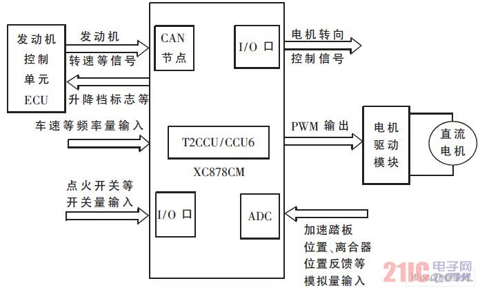
Figure 1 Schematic diagram of the automatic clutch controller 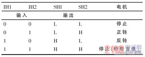
The motor drive circuit is shown in Figure 2. The MCU uses an I/O port output to control motor steering, and a PWM output to control motor speed. The two control signals are connected to the input terminals IH1, IH2 of the driver chip through an interface circuit composed of an AND gate and two NOT gates. This is to ensure that the two inputs are not high at the same time, to prevent the problem of bridge arm straight-through, and to improve the safety and reliability of the system. 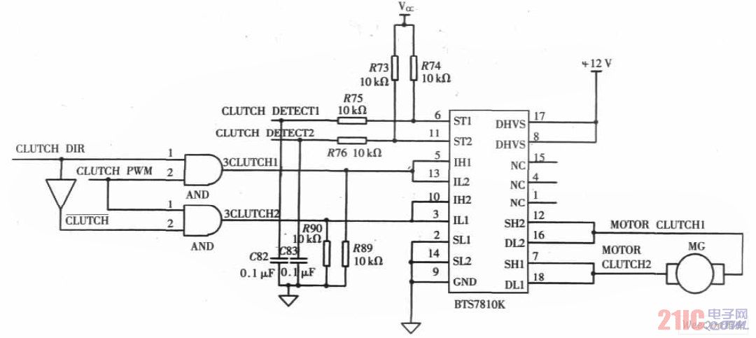
Figure 2 motor drive circuit 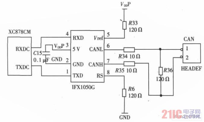
Figure 3 Interface circuit diagram of CAN node 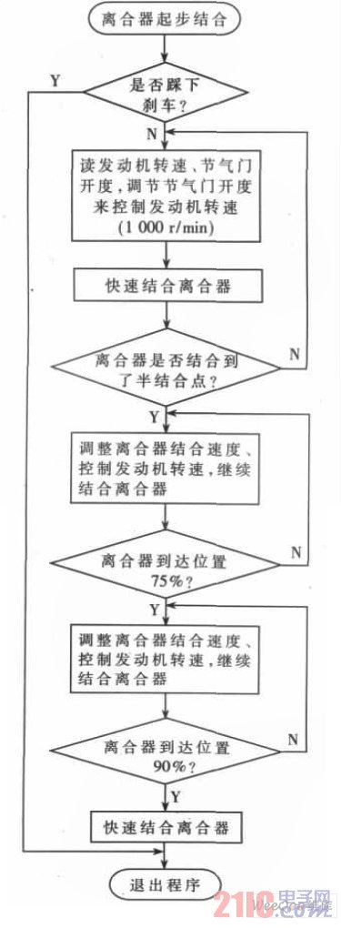
Figure 4 Start-up combined with control software flow chart 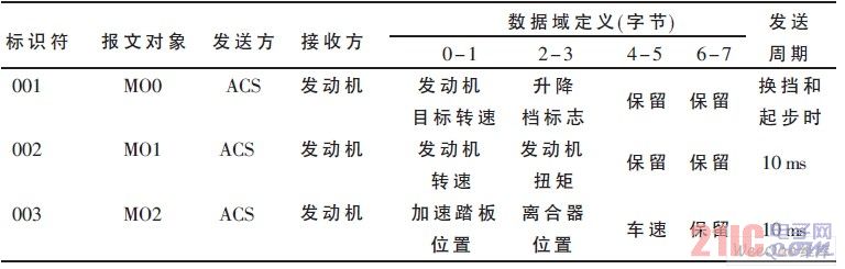
4 CAN communication test experiment 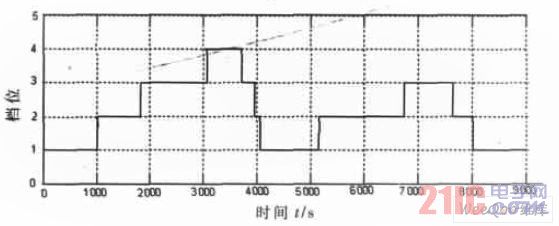
Figure 5 gear information 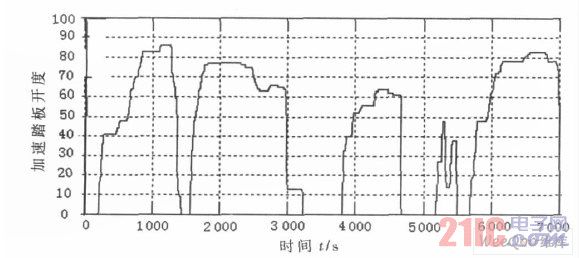
Figure 6 accelerator pedal opening signal