Medical device manufacturers can use ultra-wideband technology in various wireless applications. Ultra-wideband (UWB) is a high-bandwidth (480-1320Mb / sec) and short-distance (10-50m) wireless transmission technology that is gradually being used more in medical applications. UWB was initially developed only as a military technology, and it was not developed for commercial use until the US military decrypted it in 1994. Early UWB chipsets were designed to replace USB cables in mainstream personal computers. However, the requirements for medical applications are different, because the transmission of real-time video and ultrasound images requires low time delay and deterministic data throughput. Another factor hindering the use of UWB technology is that commercial UWB chipset suppliers require annual orders of more than hundreds of thousands. However, there are already some companies that provide UWB chipsets for the medical market demand and output. Medical device manufacturers have begun to use UWB technology for electronic endoscopes, laryngoscopes, and ultrasonic sensors. This article describes how to apply ultra-wideband technology to electronic endoscopes. Considerations for using UWB technology for endoscopy The flexible optical endoscope has a long and thin tube that can be introduced into the patient. The new endoscope contains a light source and a tiny imaging sensor at the top. By using a new type of LED light source and a micro CMOS camera, this structure is feasible. The power consumption of the LED light source at the top of the endoscope is much lower than that of the traditional high-power light source. Therefore, a small set of batteries is enough to support the endoscope for several hours. In addition, copper wires can be used to replace expensive light pipes. Another advantage is that the image can be displayed on the LCD and recorded at the same time. The wireless connection of the display eliminates the physical limitations of the endoscope, making patients and doctors more comfortable during the examination. Digital transmission is an ideal transmission method because it can provide high-definition picture quality and avoid distortion. Since the doctor observes his operations on the patient through a video monitor, the picture should appear on the screen in real time—in other words, the delay should be as short as possible. Therefore, video signals cannot pass through compression circuits or large-scale protocol stacks. UWB's high bandwidth, low latency, low radiation, and robustness make it an ideal wireless transmission technology for endoscopes. UWB radio technology The transmission of uncompressed video in NTSC quality requires a deterministic data transfer rate of at least 166 MB / sec, which cannot be achieved with traditional technologies. Traditional wireless technology uses a wireless access mechanism that depends on channel availability. This means that other devices within the receiving range may temporarily reduce the data bandwidth. If UWB technology is used, a channel is permanently reserved during the session. The protocol overhead of UWB technology is very low, which is very important to reduce the transmission delay. By dispersing the data into 128 subcarriers, a very stable wireless channel can be established. Next, other advantages and details of UWB technology will be discussed. UWB wireless communication layer Early UWB development was based on different physical (PHY) and medium access control (MAC) layer specifications. Over the past three years, the WiMedia Alliance ’s MAC layer and PHY layer specifications have been adopted by most UWB implementers. Unlike the established wireless transmission technologies (such as WLAN), UWB occupies a 528MHz frequency band for each transmission channel. In contrast, the maximum bandwidth of a wireless local area network (WLAN) channel is 20 MHz. Three 528MHz frequency bands form a frequency band group. The entire frequency range of UWB is 3.1 to 10.6 GHz and is divided into 5 frequency band groups. There are now advanced dual-band transceivers operating in band groups 1 and 3. WiMedia-UWB uses orthogonal frequency division multiplexing (OFDM) modulation technology. Each 528MH band is divided into 128 subcarriers, and the peak of each subcarrier is exactly at the zero position of the adjacent subcarrier (hence the name 'orthogonal', see Figure 1, page 27). The transmission information is allocated to these 128 subcarriers, and the maximum rate of each 528MHz channel is 480 Mb / sec. Since the sub-carriers are distributed over a large bandwidth of 528MHz, they support a very low transmit power of 37 microwatts (in contrast, the transmit power allowed by WLAN exceeds 300 mW). The broadband and ultra-low transmission power suitable for information transmission make UWB coexist with other radio frequencies in the radio frequency (RF) field. Although the transmission power is only 37 microwatts, its transmission distance can reach 10 meters, and it can pass through a 25 cm thick brick wall without affecting the signal transmission. Please note that the peak of each subcarrier is at the zero point of its adjacent subcarrier Media access control layer The UWB wireless communication layer is responsible for radio frequency (RF) processing, while the media access control layer is responsible for managing the UWB network and controlling wireless communication status. When several UWB devices are close together, they form a so-called ad hoc network. The peer-to-peer network is not a pre-planned network, but is constructed by participating devices in close proximity, and participating devices can join and exit as appropriate. Figure 2 shows a point-to-point network constructed by three UWB devices. Among them, the device A is invisible to the device C. Even if device A on the left side of the figure cannot "listen" to device C, it is possible to know the existence of device C and the time slot it occupies, because device A can learn about the device through the so-called "beacon" C. Beacons contain information about neighboring devices, so devices can know each other. Direct transmission of data in any direction is possible between all devices that can receive information from each other. UWB uses Time Division Multiple Access (TIme Division MulTIple Access, TDMA) mode, that is, organizes transmission according to time slots and frames. The combination of UWB transmission time slots constitutes a superframe (see Figure 4). The superframe is divided into a beacon segment (BP) and a data transmission segment (DTP). Beacons and valid data occupy 256 media access slots of the superframe, one media access slot lasts 256 μs, and one superframe lasts 65.5 ms. All network members that can "listen" to each other are synchronized with the superframe through the beacons heard. The information in the beacon can be regarded as a communication channel for network members. Since channels are organized by time slots, it is not necessary for each device to receive and send data at all times. A device only needs to be woken up every 65.5ms to listen to the beacon; if the device has no tasks, it will return to sleep, similar to the sleep mode of the mobile phone to extend battery life. This extends the operating time of the battery-powered system. UWB's wireless interface is much like a cable: if there are multiple communication members and the channel is limited, access rights must be managed. When intending to send information to a channel, the device member needs to "listen" to determine whether the channel is already occupied by another device. If it finds that the channel is free, it sends a message. Of course, it is possible for two devices to listen to the channel at the same time and find that it is idle and send information to it at the same time. This is called "conflict". When a "conflict" occurs, the device will try to access the channel later. During this period, each device waits for a random duration before retrying. Devices with higher priority may retry before devices with lower priority. This "competitive access" mechanism was invented with Ethernet in the 1970s and is also commonly used in WLAN. Obviously, if you want to continuously transmit a video stream with the lowest delay, this method will not work. To ensure the uninterrupted transmission of video streams, UWB uses a distributed resident protocol (DRP). Because UWB is based on TDMA, network members can reserve some fixed time slots (media access time slots) to ensure communication with another device. The relevant information of the reserved channel occupied time slot is transmitted in the beacon period. If a time slot is marked as "hard reserved", no third party can occupy the time slot. This is necessary to guarantee the deterministic data transmission rate required by the video transmission. Patch Panel,48 ports patch panel,half U patch panel,patch panel 24 port NINGBO UONICORE ELECTRONICS CO., LTD , https://www.uonicore.com
Figure 1 WiMedia-UWB each 528 MHz band is divided into 128 subcarriers. 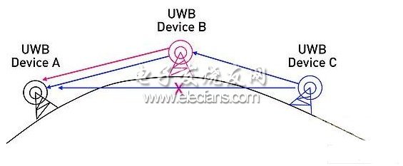
Figure 2 Description of three UWB devices in a point-to-point network 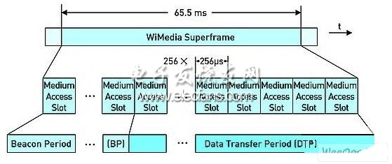
Figure 3 The super frame is divided into a beacon segment (BP) and a data transfer segment (DTP)